Remote seal process pressure measuring system

a technology of remote sealing and process pressure, which is applied in the direction of pressure difference measurement between multiple valves, instruments, nuclear elements, etc., can solve the problems of potential inaccuracy in the measured pressure and other problems

Active Publication Date: 2014-04-03
ROSEMOUNT INC
View PDF8 Cites 33 Cited by
  • Summary
  • Abstract
  • Description
  • Claims
  • Application Information

AI Technical Summary

Problems solved by technology

In specific applications where great temperature differences between ambient and process temperatures are encountered in the environment surrounding the remote seals, the remote seals may perform poorly (or are not configurable at all for these applications) and this leads to potential inaccuracies in the measured pressure and other problems.

Method used


Image

  • Remote seal process pressure measuring system
  • Remote seal process pressure measuring system
  • Remote seal process pressure measuring system

Examples


second embodiment

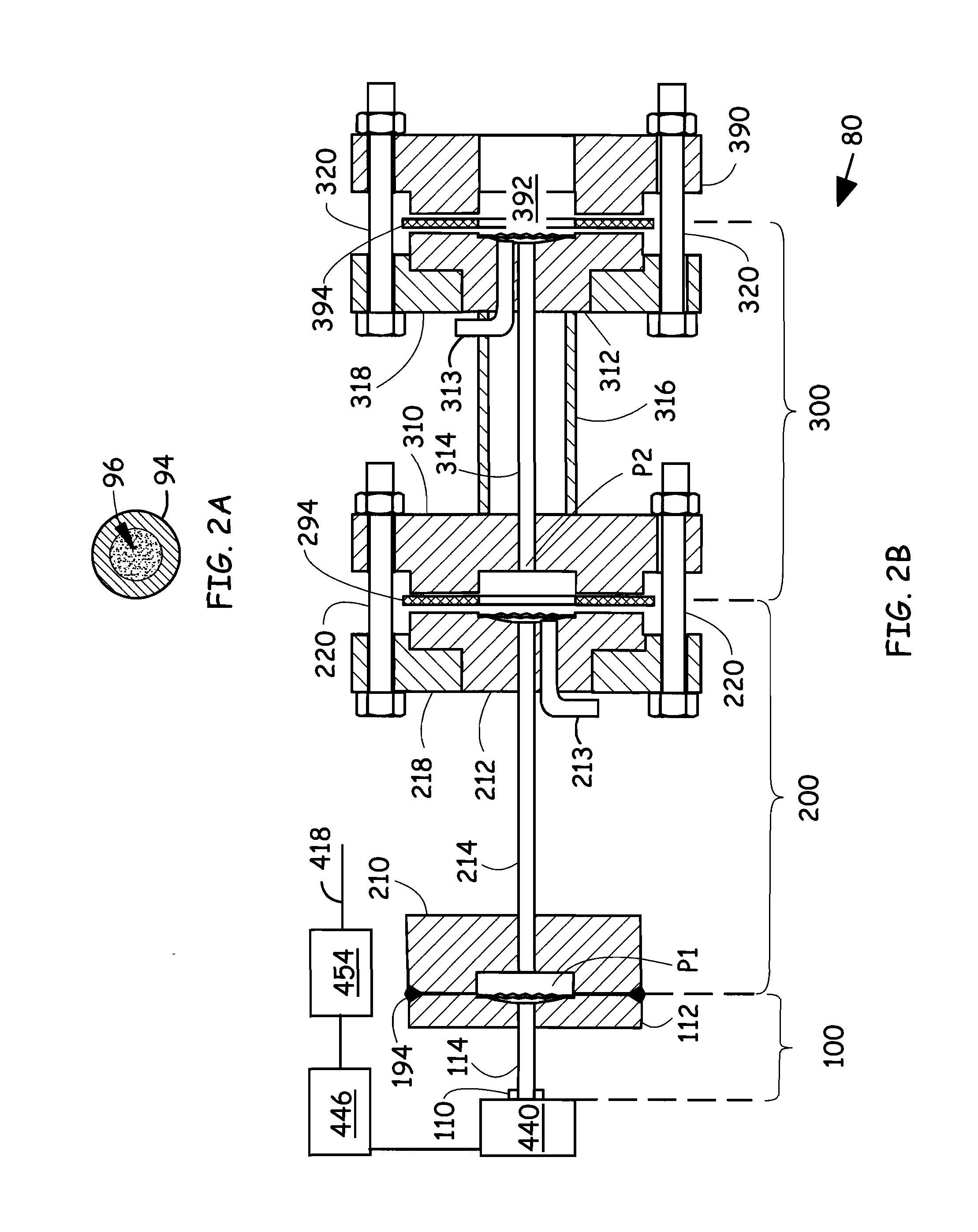
[0047]FIGS. 5A-5B illustrate a process pressure measuring system 600. The process pressure measuring system 600 includes a first sealed system 610 in a pressure transmitter 612, a second sealed system 620, and a third sealed system 630. The process pressure measuring system 600 is internally configured in the same manner as shown in FIG. 2B. The first sealed system 610 and the second sealed system 620 are closely coupled to one another as illustrated, and are located in an environment in which the temperature may drop below 0 degrees Centigrade. The third sealed system 630 is coupled to a hot process flange (not illustrated) that is at a temperature in excess of 300 degrees Centigrade. The process measuring system 600 and the process measuring system 100 (FIG. 1) are functionally similar, and illustrate local and remote mounting options to accommodate different installation mounting requirements.

[0048]FIG. 6 illustrates a second embodiment of a third sealed system 700, comparable to...

third embodiment

[0052]FIG. 7 illustrates a third sealed system 800. The third sealed system 800 includes a third pressure outlet 810, a third isolator diaphragm assembly 812, couplable to a high temperature source (flange 390, FIG. 2B) , and a third capillary passage 814 filled with a high temperature isolator fluid that couples process pressure from the third isolator diaphragm assembly 812 through the third pressure outlet 810. The third pressure outlet 810 is open and is not covered by an isolator diaphragm. An optional washer 808 can be secured in the inlet 810, if needed, to reduce a volume of fill fluid in the inlet 810.

[0053]The third sealed system comprises a support tube 816 that extends between the third pressure outlet 810 and the third isolator diaphragm assembly 812. According to one embodiment, the support tube 816 is welded to the third pressure outlet 810 and the third isolator diaphragm assembly 812, and provides mechanical support and protection for the third capillary passage 814...


PUM

PropertyMeasurementUnit
temperatureaaaaaaaaaa
temperaturesaaaaaaaaaa

Abstract

A process pressure measuring system includes a transmitter having a first sealed system in which a first outlet couples to a pressure sensor, a first isolator diaphragm assembly, a first capillary passage, and a first isolation fluid. The first isolation fluid couples a first pressure from the first isolator diaphragm to the first outlet and the pressure sensor. A second sealed system includes a second pressure outlet that is coupled to the first isolator diaphragm assembly, a second isolator diaphragm assembly, a second capillary passage and a second isolation fluid. The second isolation fluid is adapted for use in a first temperature range and couples a pressure from the second isolator diaphragm assembly to the second pressure outlet. A third sealed system includes a third pressure outlet that is coupled to the second isolator diaphragm assembly, a third isolator diaphragm assembly, a third capillary passage and a third isolation fluid. The third isolator fluid is adapted for use in a second temperature range and couples a process pressure to the third pressure outlet.

Description

BACKGROUND OF THE INVENTION[0001]The present invention relates to remote seal systems for use with industrial process pressure transmitters. More specifically, the present invention relates to such remote seal systems used in extreme temperature environments.[0002]Industrial process control systems are used to monitor and control industrial processes used to produce or transfer fluids or the like. In such systems, it is typically important to measure “process variables” such as temperatures, pressures, flow rates, and others. Process control transmitters are used to measure such process variables and transmit information related to the measured process variable back to a central location such as a central control room.[0003]One type of process variable transmitter is a pressure transmitter which measures pressure of a process fluid and provides an output related to the measured pressure. This output may be a pressure, a flow rate, a level of a process fluid, or other process variabl...

Claims


Application Information

Patent Timeline
Patent Type & Authority Applications(United States)
IPC IPC(8): G01L19/06
CPCG01L19/0618G01L19/0046G01L19/0681G01L27/007G01L13/026
Inventor MILLER, BRENT WAYNEFADELL, PAUL RYAN
Owner ROSEMOUNT INC
Why Eureka
Try Eureka