Image Forming Apparatus

Active Publication Date: 2014-04-03
BROTHER KOGYO KK
View PDF1 Cites 1 Cited by
  • Summary
  • Abstract
  • Description
  • Claims
  • Application Information

AI Technical Summary

Benefits of technology

[0008]The present invention is advantageous in that an image forming apparatus, which includes resi

Problems solved by technology

While the resin frames tend to be less rigid compared to the metal frames, however, it may be difficult to maintain drivable

Method used


Image

  • Image Forming Apparatus
  • Image Forming Apparatus
  • Image Forming Apparatus

Examples


Example

[0026]Hereinafter, an embodiment of the present invention will be described with reference to the accompanying drawings. It is noted that various connections are set forth between elements in the following description. These connections in general, and unless specified otherwise, may be direct or indirect, and this specification is not intended to be limiting in this respect.

[0027]1. Overall Configuration of Image Forming Apparatus

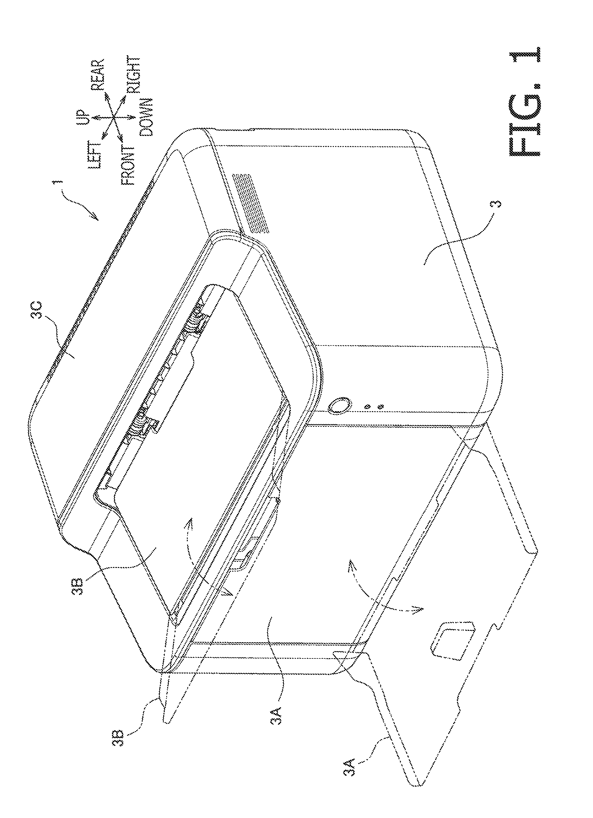
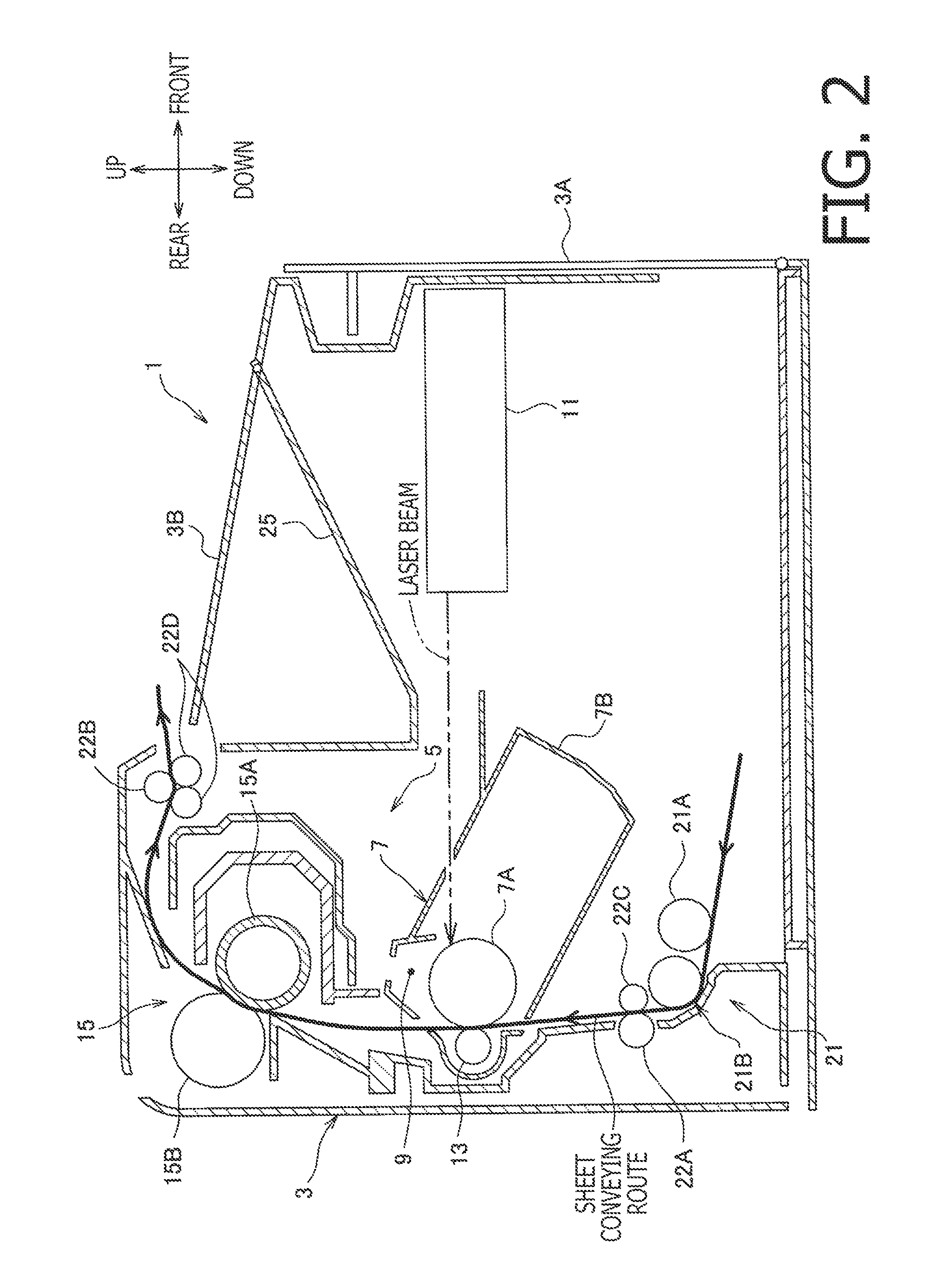
[0028]An overall configuration of an image forming apparatus 1 according to the embodiment will be described with reference to FIG. 1. In the following description, directions concerning the image forming apparatus 1 will be referred to in accordance with orientation indicated by arrows in the drawings. The image forming apparatus 1 being a monochrome image forming apparatus includes a chassis 3, which accommodates an image forming unit 5 inside. On a front face of the chassis 3, a swingable sheet-feeder cover 3A is attached. On top of the chassis 3, a swi...


PUM


Abstract

An image forming apparatus, including an image forming unit; a resin-made frame to support the image forming unit; a drive source arranged on a one-end side of a transmission path to generate driving force; a gear arranged on the other-end side of the transmission path to be rotated, while one of axial ends of a shaft of the gear is supported by the frame; a metal-made first supporting member fixed to the frame to support the other of axial ends of the shaft of the gear thereon; a metal-made second supporting member fixed to the frame to support the drive source thereon and; an endless belt; a first pulley supported by the second supporting member to transmit the driving force to the endless belt, the first pulley being; and a second pulley having the endless belt strained there-around and supported by the first supporting member, is provided.

Description

CROSS REFERENCE TO RELATED APPLICATION[0001]This application claims priority from Japanese Patent Application No. 2012-216229, filed on Sep. 28, 2012, the entire subject matter of which is incorporated herein by reference.BACKGROUND[0002]1. Technical Field[0003]An aspect of the present invention relates to an image forming apparatus for forming an image on a sheet.[0004]2. Related Art[0005]An image forming apparatus having lateral plates, on which gears to be drive to operate various kinds of rollers are attached, is known. The gears may be driven by driving force, which is generated in an electric motor and transmitted to the gears via a toothed belt.[0006]In general, a frame assembly in such an image forming apparatus, including the lateral plates, may be required to be substantially rigid. Therefore, the frame assembly is often equipped with metal-made frames. On the contrary, in consideration of manufacturing cost reduction, resin-made frames may be preferable.SUMMARY[0007]While...

Claims


Application Information

Patent Timeline
IPC IPC(8): G03G15/00
CPCG03G15/757G03G21/1857
Inventor MIWA, ATSUSHIYAMAMOTO, TOMOYA
Owner BROTHER KOGYO KK
Why Eureka
Try Eureka