Wooden Member Joint Structure

Active Publication Date: 2014-04-03
SUMITOMO FORESTRY CO LTD
View PDF14 Cites 8 Cited by
  • Summary
  • Abstract
  • Description
  • Claims
  • Application Information

AI Technical Summary

Benefits of technology

[0030]In this wooden member joint structure, a tensile force applied to the joint bolt is transferred from the proximal end of the joint bolt to the screw member, and acts as an axial force on the screw member. Then, the force is transferred from the outer peripheral surface of the screw member to the wooden member. At this time, because a compressive force is applied to the portion of the screw member on the pulling side from the location where the joint bolt is threaded with the screw member and a tensile force is applied to the portion of the screw member proximal to the location where the joint bolt is secured thereto, a force is distributed over a wide range in the axial direction of the screw member when transmi

Problems solved by technology

It is generally known that the greater the amount of plastic deformation or deformation a

Method used


Image

  • Wooden Member Joint Structure
  • Wooden Member Joint Structure
  • Wooden Member Joint Structure

Examples


Example

[0051]Description is hereinafter made of embodiments of the present invention with reference to the drawings.

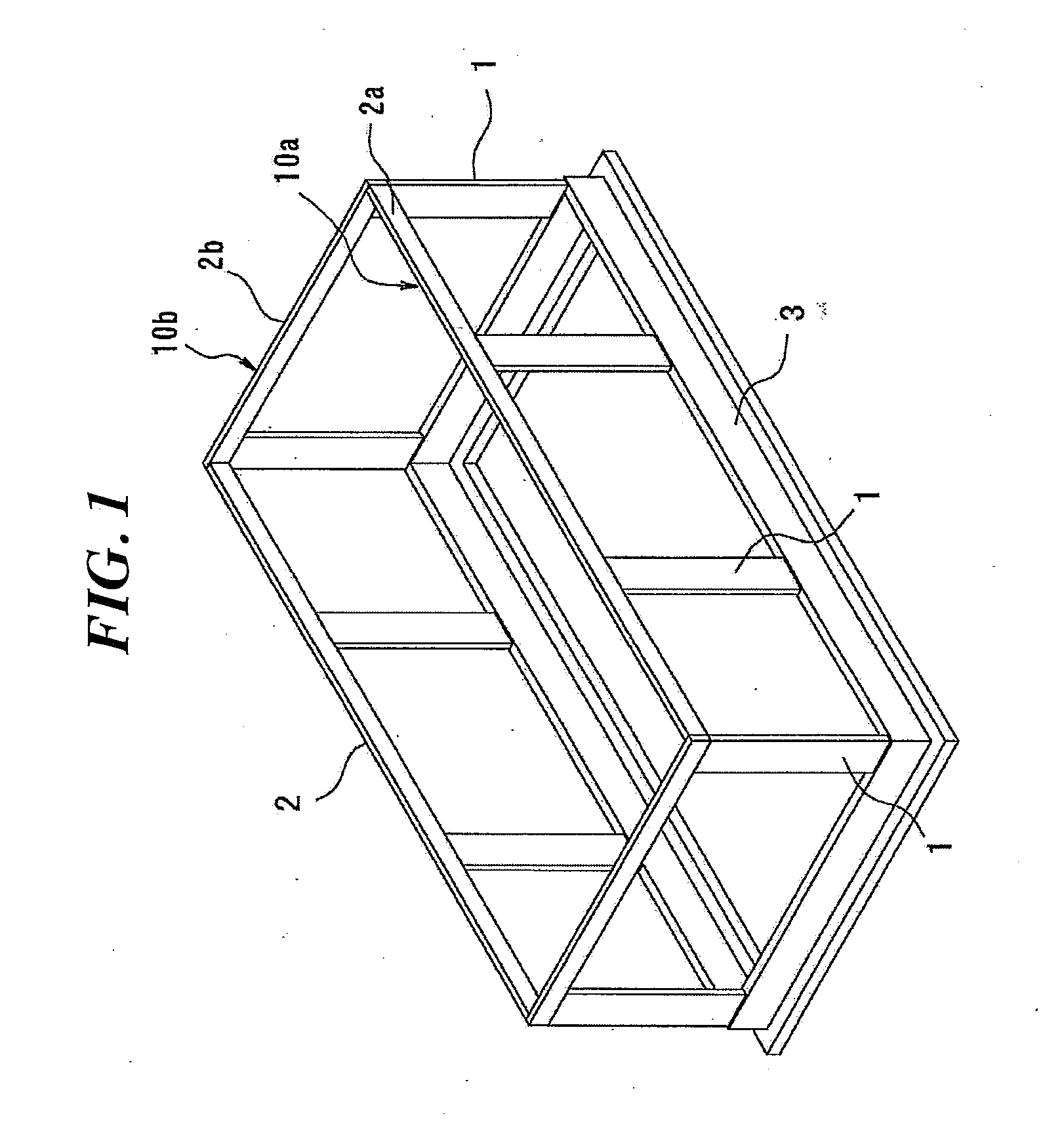
[0052]FIG. 1 is a schematic perspective view, illustrating a skeleton of a wooden building in which a wooden member joint structure according to an embodiment of the present invention is suitably used.

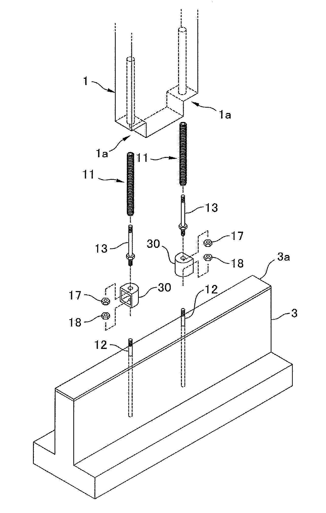
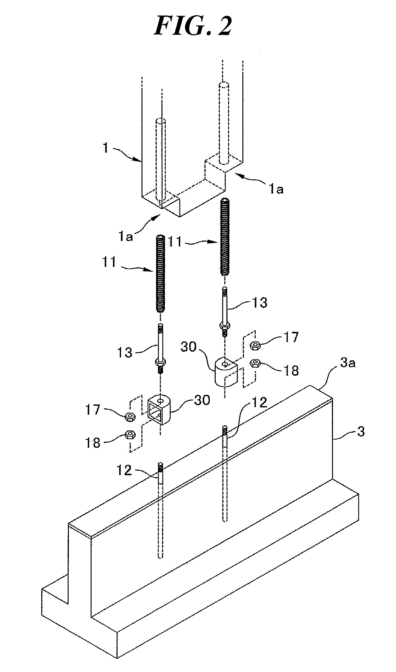
[0053]The skeleton has a rigid flume body 10 in which wooden columns 1 are joined to a wooden beam 2 and a foundation 3 in such a way that a bending moment can be transferred between the columns 1 and the beam 2 and between the columns 1 and the foundation 3, and is formed by combining a plurality of rigid frame bodies 10 on the concrete foundation 3. Each rigid frame body 10 has what is called a beam-priority structure formed by joining a wooden beam 2 mounted on wooden columns 1 thereto. The column 1 of each rigid frame body 10 has a flat rectangular cross-section with a long side extending in the axial direction of the beam 2 supported thereon and a short side extending in a ...


PUM


Abstract

A wooden member joint structure having high strength against load repeatedly applied in opposite directions, with improved work efficiency in joining the wooden member to a mating member. A screw member having spiral protrusion on its outer peripheral surface and an axial hollow hole is threaded axially into a wooden column. A distal end of joint bolt is threadedly engaged with bottom of the hollow hole. The joint bolt has an integrally formed flange, and the flange is threaded into the column together with the screw member with its contact surface firmly pressed against end face of the screw member. A joint device is clamped between a fastening nut threadably mounted on a proximal end of the joint bolt and the flange and coupled to the screw member via the joint bolt. The joint device is secured to a foundation by an anchor bolt protruding therefrom and a fastening nut.

Description

BACKGROUND OF THE INVENTION[0001]1. Technical Field[0002]The present invention relates to a wooden member joint structure for use in joining a wooden column to a mating member, such as a wooden beam or foundation, in a wooden building, and, more particularly, to a structure in which a screw member threaded into a wooden member is joined to a mating member via a joint device.[0003]2. Related Art[0004]It is proposed to join a wooden column to a wooden beam, foundation or the like by a so-called rigid joint that allows a bending moment to be transferred therebetween to form a skeleton having a rigid-frame structure in a wooden building. When a horizontal force is repeatedly applied to such a structure alternately in opposite directions during an earthquake, for example, a bending moment acts on the joint between the column and the beam or foundation. The joint needs to maintain sufficient strength against such a bending moment.[0005]A joint structure for a rigid-frame structure using a...

Claims


Application Information

Patent Timeline
IPC IPC(8): F16B9/02
CPCF16B9/026E04B1/4157E04B5/12F16B5/0275F16B5/0291F16B37/125Y10T403/36
Inventor IMAI, JUNICHIISHIYAMA, HIROKINAKASHIMA, HIROKI
Owner SUMITOMO FORESTRY CO LTD
Why Eureka
Try Eureka