MRI catheter with resonant filter

a resonant filter and magnetic resonance imaging technology, applied in the field of magnetic resonance imaging, can solve problems such as affecting the overall quality of images

Inactive Publication Date: 2014-04-03
BIOSENSE WEBSTER (ISRAEL) LTD
View PDF4 Cites 6 Cited by
  • Summary
  • Abstract
  • Description
  • Claims
  • Application Information

AI Technical Summary

Problems solved by technology

While present-day MRI systems may provide good images, some images may include artifacts which can detract from the overall quality of the images.

Method used


Image

  • MRI catheter with resonant filter
  • MRI catheter with resonant filter
  • MRI catheter with resonant filter

Examples


Embodiment Construction

Overview

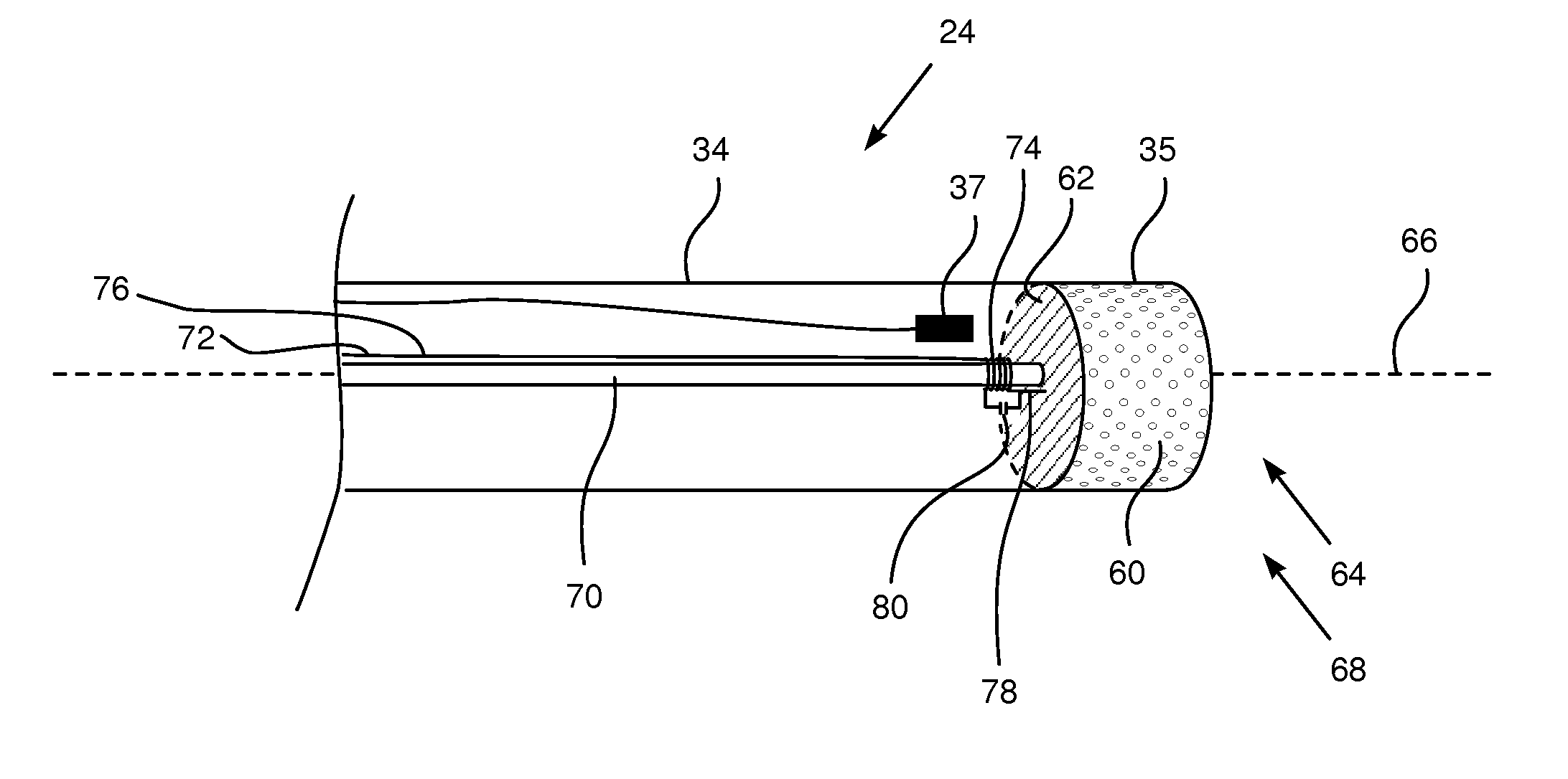
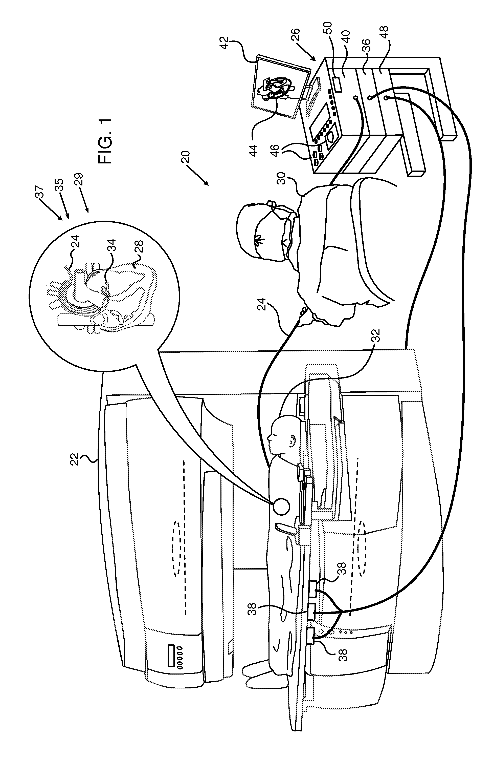
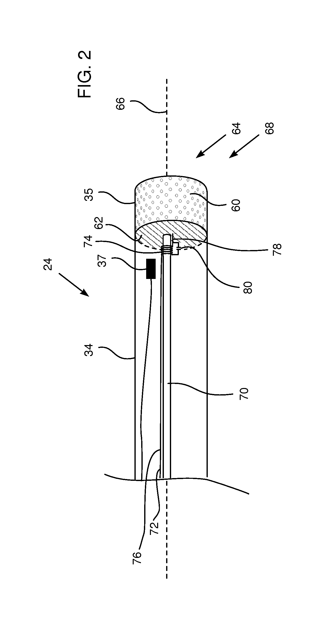
[0026]An embodiment of the present invention provides a medical probe which is suitable for operating in a magnetic resonance imaging (MRI) environment. The probe comprises a flexible insertion tube which has a distal end for insertion into a body cavity, such as a section of a heart, and the cavity is imaged using MRI techniques. An electrode is attached to the distal end of the insertion tube so as to make electrical contact with tissue in the body cavity. The electrode may typically be used for transferring radio-frequency (RF) ablation energy to the tissue, and / or for sensing electrophysiological signals generated at the tissue.

[0027]A coil is electrically coupled between the electrode and an electrical lead which runs through the insertion tube between the distal and proximal ends of the tube. An inductance of the coil is selected so that the lead, the coil and the electrode form a resonant circuit having a resonant frequency in a range between 1 MHz and 300 MHz, typica...


PUM


Abstract

A medical probe includes a flexible insertion tube having a distal end for insertion into a body cavity and having a proximal end. The probe further includes an electrode attached to the distal end of the insertion tube and configured to make electrical contact with tissue in the body cavity. An electrical lead runs through the insertion tube between the distal and proximal ends. In addition a coil is electrically coupled between the electrode and the lead in the insertion tube so as to define a resonant circuit having a resonant frequency in a range between 1 MHz and 300 MHz.

Description

FIELD OF THE INVENTION[0001]The present invention relates generally to magnetic resonance imaging, and specifically to reducing artifacts produced during the imaging.BACKGROUND OF THE INVENTION[0002]Magnetic resonance imaging (MRI) is an extremely powerful technique for visualizing tissue, particularly soft tissue, of a patient. The technique relies on exciting nuclei, typically hydrogen nuclei, from their equilibrium state, and measuring the resonant radio-frequency signals emitted by the nuclei as they relax back to equilibrium. While present-day MRI systems may provide good images, some images may include artifacts which can detract from the overall quality of the images.[0003]Documents incorporated by reference in the present patent application are to be considered an integral part of the application except that to the extent any terms are defined in these incorporated documents in a manner that conflicts with the definitions made explicitly or implicitly in the present specific...

Claims


Application Information

Patent Timeline
Patent Type & Authority Applications(United States)
IPC IPC(8): A61B5/055
CPCA61B5/055A61B5/062G01R33/287G01R33/34084
Inventor GOVARI, ASSAFBEECKLER, CHRISTOPHER THOMASPAPAIOANNOU, ATHANASSIOS
Owner BIOSENSE WEBSTER (ISRAEL) LTD
Why Eureka
Try Eureka