
Carbonation Device
a carbonation device and carbonation technology, applied in the direction of gas purification by liquid washing, fuel injection apparatus, volume measurement, etc., can solve the problems of inability to be configured by the user, difficult coupling procedure, and sometimes unreliable mechanisms, so as to simplify the domestic carbonation process
- Summary
- Abstract
- Description
- Claims
- Application Information
AI Technical Summary
Benefits of technology
Problems solved by technology
Method used
Image

Examples
Embodiment Construction
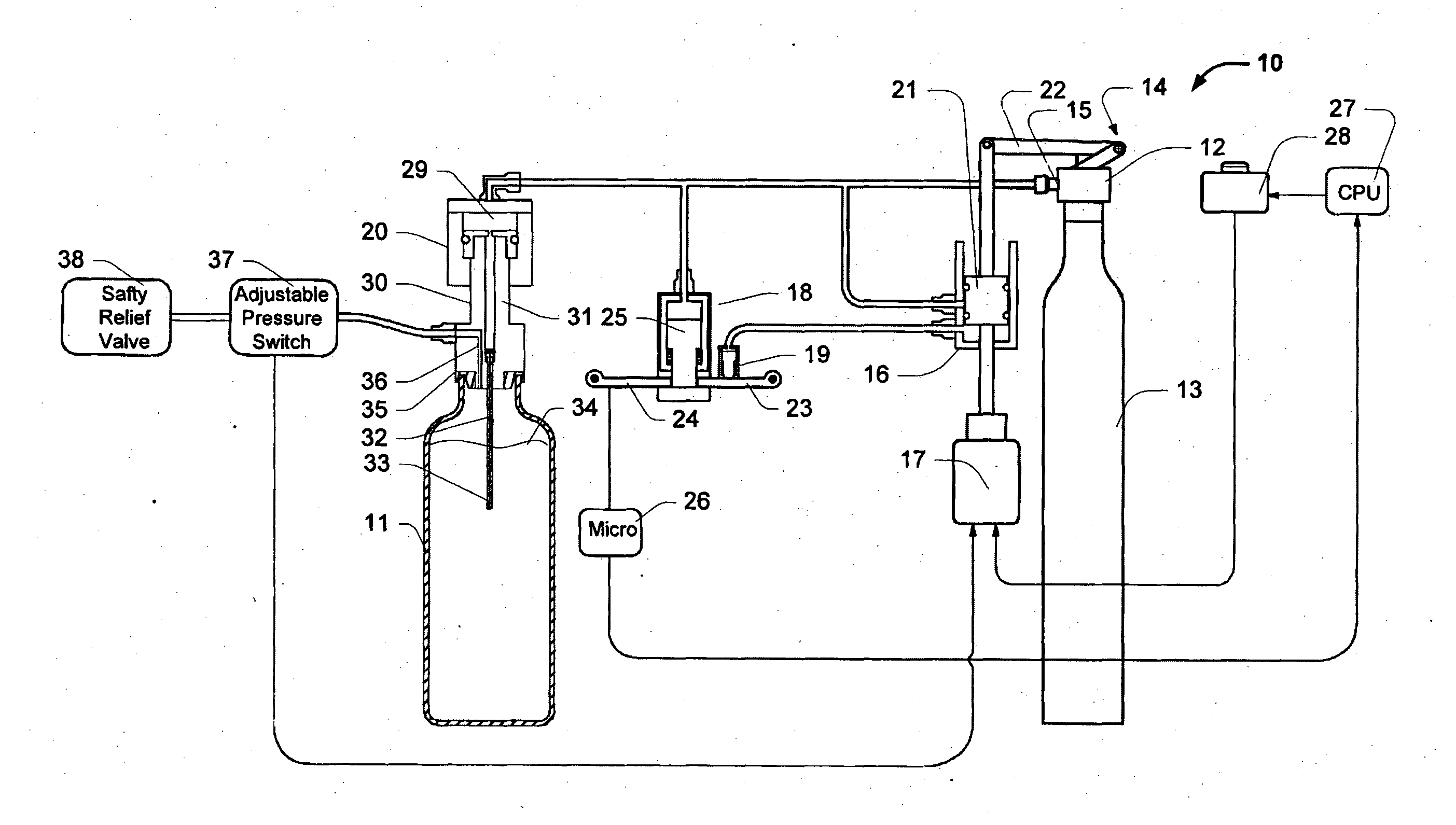
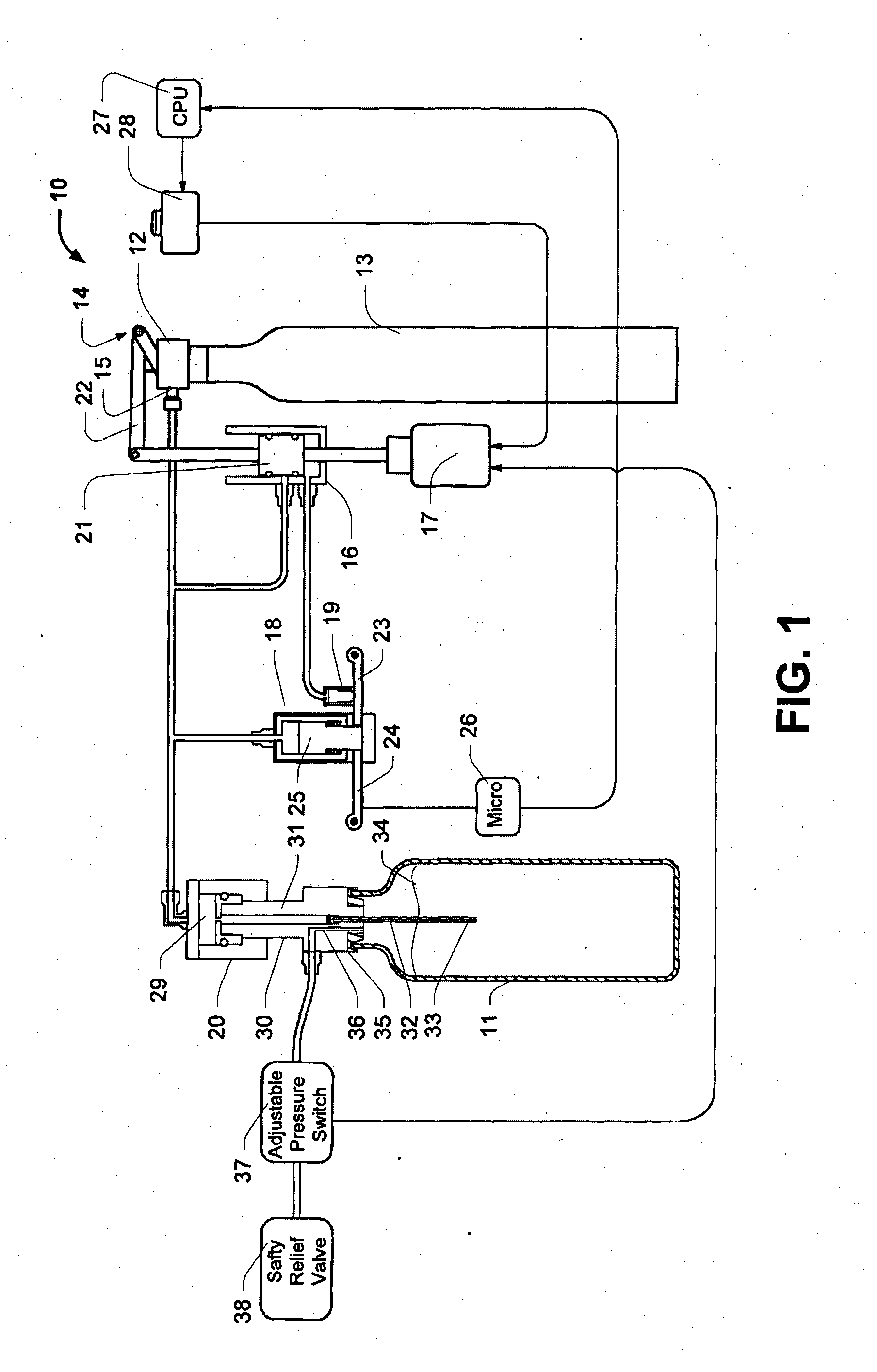
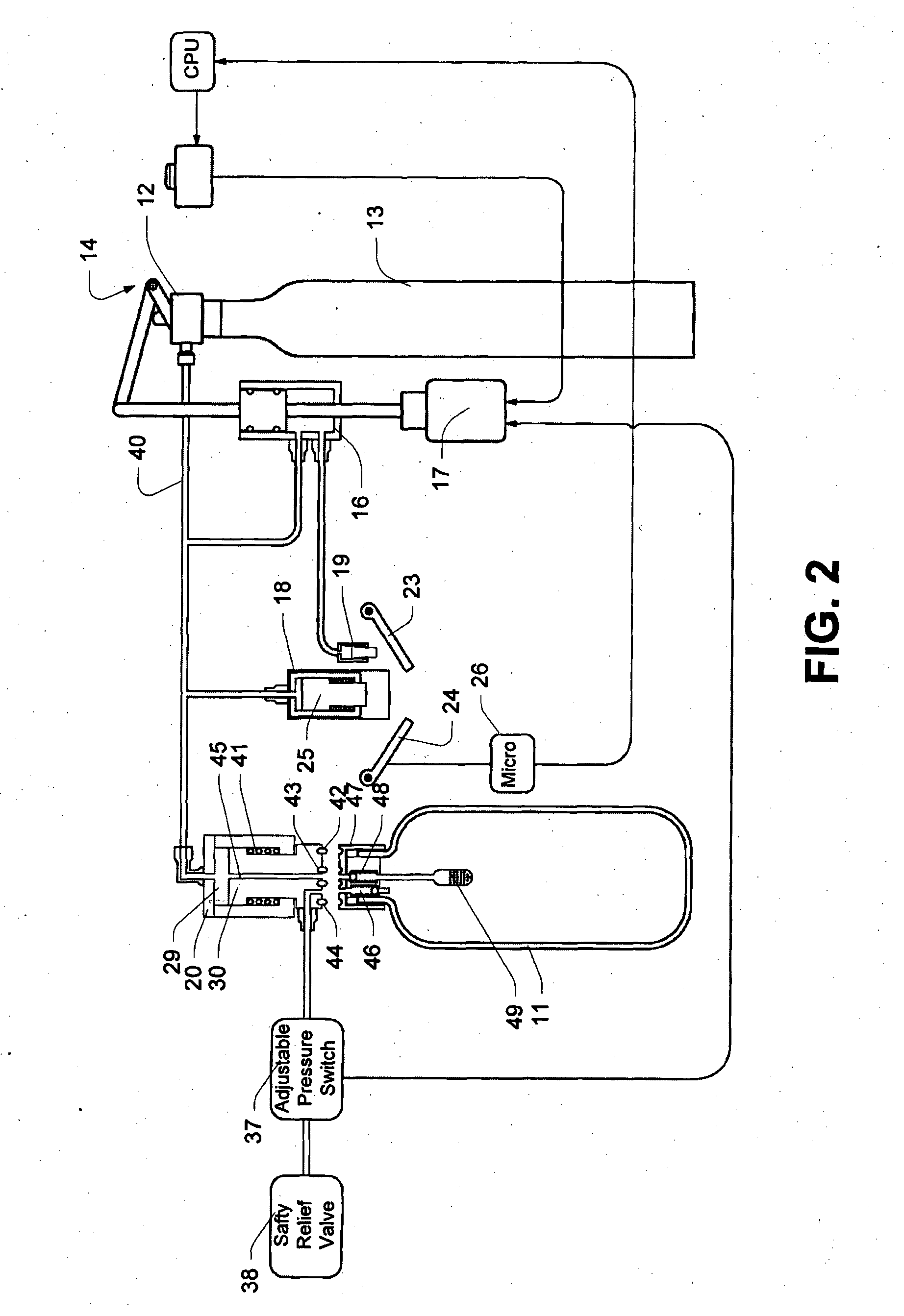
[0046]As shown in FIG. 1, a device 10 for force carbonating the liquid in a bottle with no thread or bayonet fitting to connect it with a fill head. The device has a primary dispensing coupling or valve 12 that is adapted to receive an interchangeable carbon dioxide (CO2) cylinder 13. The valve 12 includes an activation assembly 14 and an outlet 15. The outlet supplies CO2 to components required by the carbonator 10, through a network of suitable piping or tubing. CO2 from the cylinder 13 is supplied to a diverter valve 16 that is activated by (for example) a solenoid 17. CO2 is also selectively routed to a locking assembly 18, a door opening apparatus 19 and bottle fill head assembly 20.
[0047]As shown in FIG. 1, the solenoid 17 and diverter 16 are shown in a “fill” orientation. In this orientation, a piston 21 in the diverter allows pressurised CO2 flows through to those locations where pressurised CO2 is required but not to the door opening mechanism 19. A mechanical linkage 22 fr...
PUM
| Property | Measurement | Unit |
|---|---|---|
| Pressure | aaaaa | aaaaa |
| Size | aaaaa | aaaaa |
| Volume | aaaaa | aaaaa |
Abstract
Description
Claims
Application Information