Flexible expansion joint

a flexible expansion joint technology, applied in the direction of adjustment joints, pipe joints, screw threaded joints, etc., can solve the problems of metal bellows expansion joints that cannot be easily deformed, liable to subject to metal fatigue, etc., and achieve the effect of simple appearance and high safety of the function of the third length limiter

Active Publication Date: 2014-04-10
VICTAULIC OF JAPAN
View PDF25 Cites 8 Cited by
  • Summary
  • Abstract
  • Description
  • Claims
  • Application Information

AI Technical Summary

Benefits of technology

[0045]The third stopper includes the slotted plate having one end attached to either the first fixed member or the second fixed member and provided with the third axial slot, and the guide member having one end attached to either the second fixed member or the first fixed member and a guide part fitted in the third slot. Therefore, the third length limiter can be easily and firmly formed.
[0046]Since the third stopper includes the third string of the predetermined third limit length, the third length limiter can be formed in a simple mechanism.
[0047]The third length limiter includes the first protrusion protruding from the outside surface of one axial end of the first sleeve, and the second protrusion protruding from the inside surface of the other axial end of the outer sleeve and capable of coming into contact with the first protrusion. The first and the second protrusion come into contact with each other to ensure that the distance between the first and the second reference holder does not exceed the predetermined third limit length equivalent to an allowable limit length at a length below which the third sealing member can maintain the gap between the first sleeve and the outer sleeve in a liquid-tight sealed state, and third length limiter is interposed between the first sleeve and the outer sleeve. Therefore, the third length limiter is concealed from view from outside and has a simple appearance. The third length limiter will not be directly shocked by external impacts and, hence high safety of the function of the third length limiter can be ensured.

Problems solved by technology

Metal bellows expansion joints deform repeatedly to deal with the bending and expansion of pipelines and hence are liable to subject to metal fatigue.
Considerably strong force needs to be applied to metal bellows expansion joints to deform the same and hence metal bellows expansion joints cannot be easily deformed.

Method used


Image

  • Flexible expansion joint
  • Flexible expansion joint
  • Flexible expansion joint

Examples


first embodiment

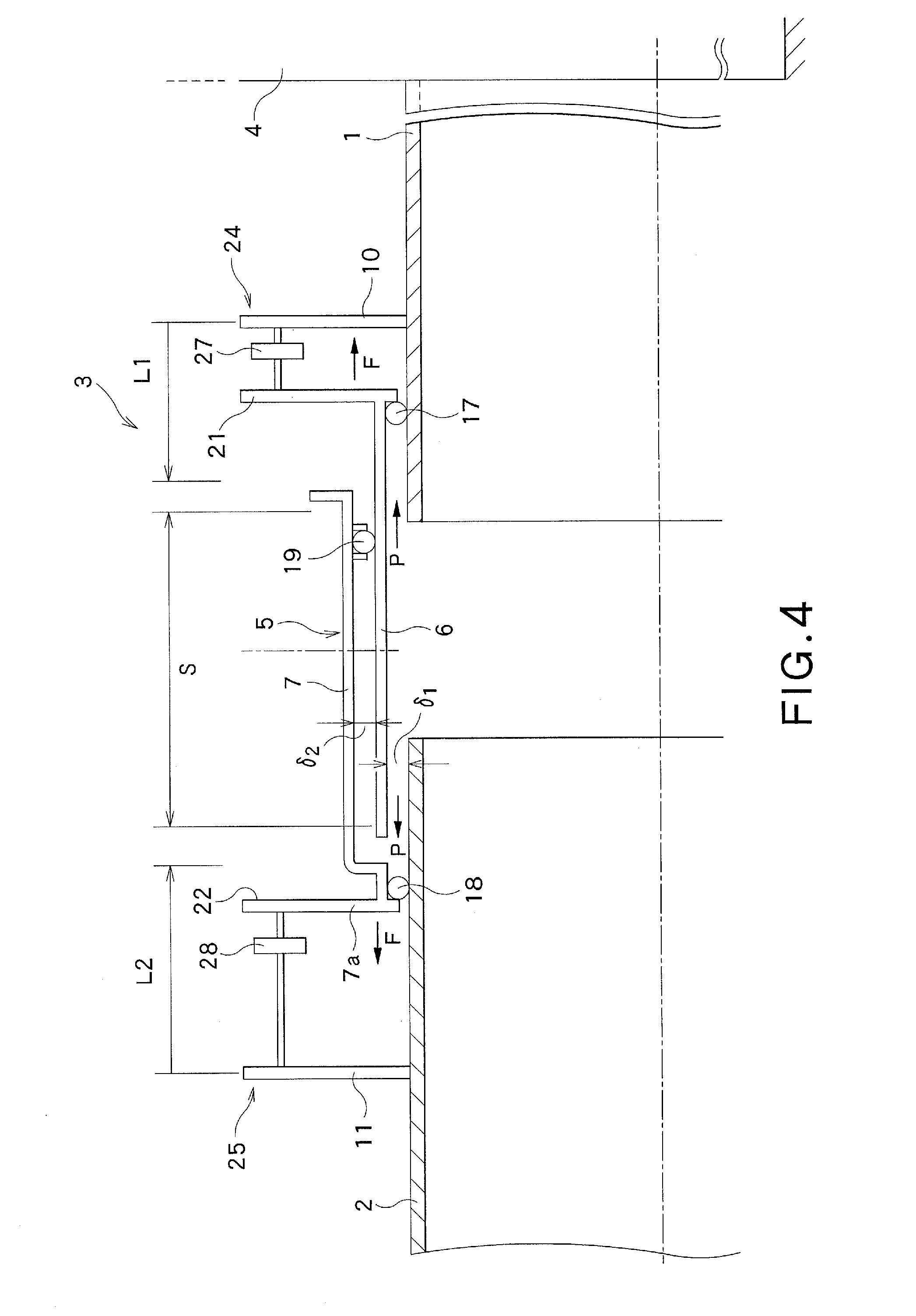
[0090]the present invention will be described with reference to FIG. 4.

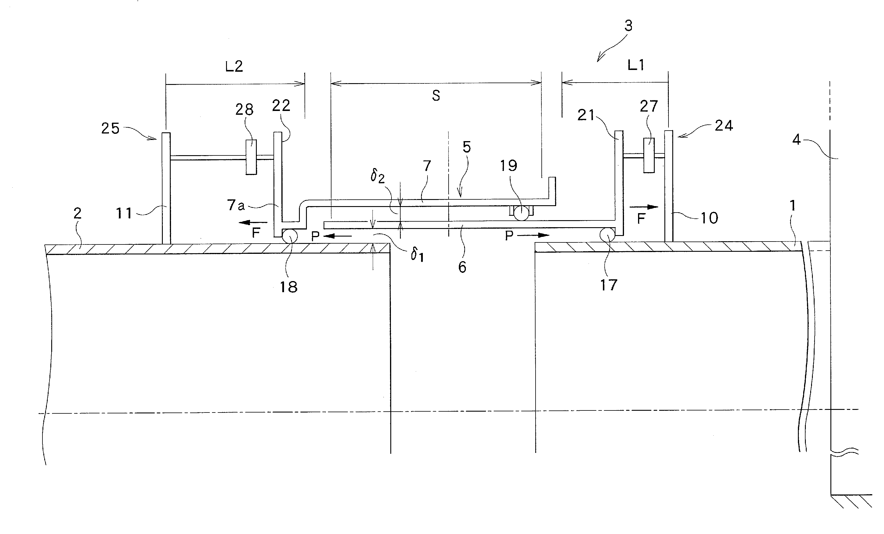
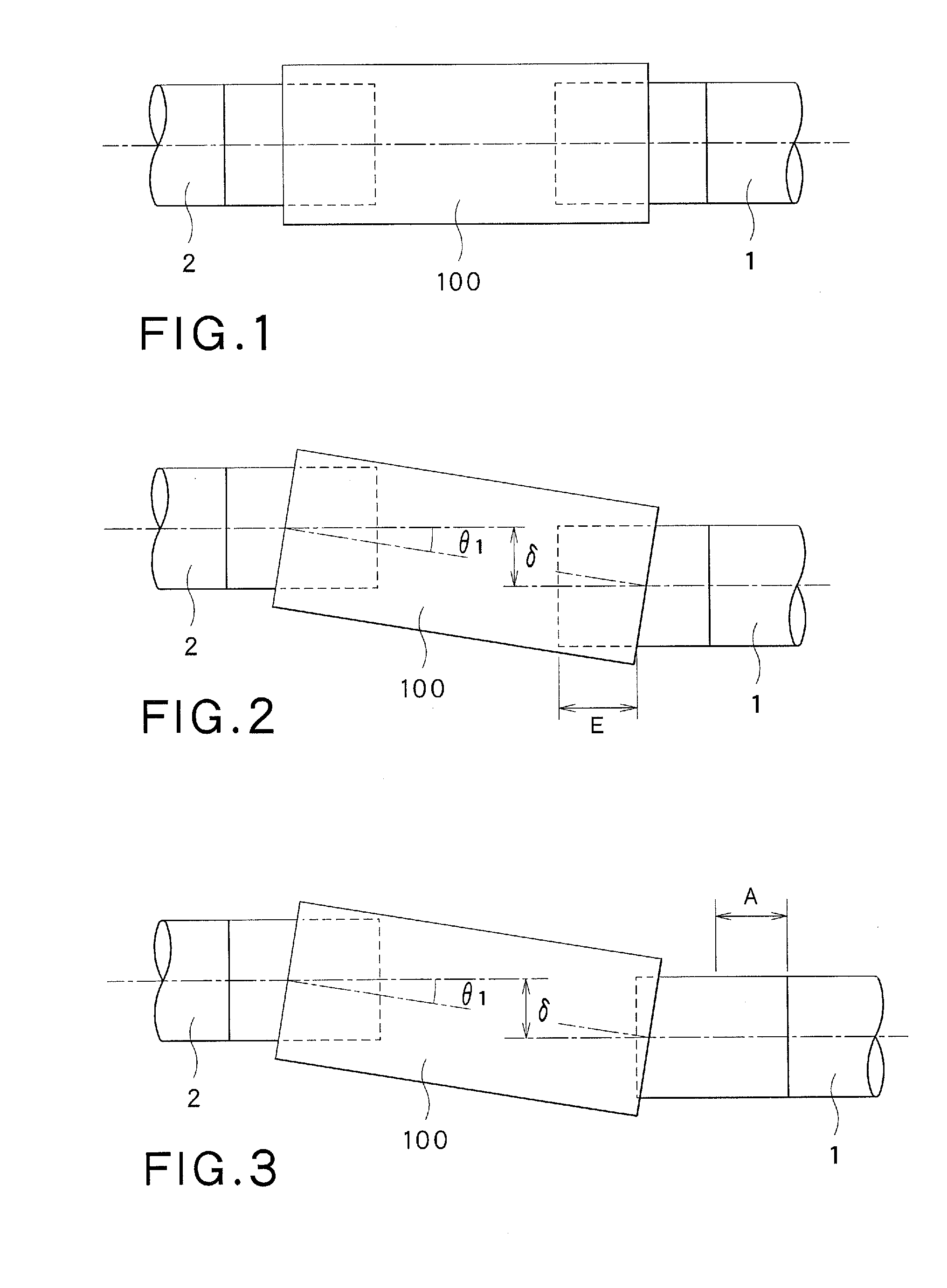
[0091]Referring to FIG. 4, a first pipe 1 is connected to a building built, for example, in a hydraulic power station and is connected to a second pipe 2 by a flexible expansion joint 3 provided with a tubular sleeve 5 such that the pipes 1 and 2 are bendable relative to each other and the distance between the pipes 1 and 2 is changeable. The first pipe 1, the second pipe 2 and the flexible expansion joint 3 are laid in the sea or laid underground.

[0092]The sleeve 5 of the flexible expansion joint 3 includes a tubular first sleeve 6 put on an end part of the first pipe so as to surround the respective end parts of the first pipe 1 and the second pipe 2, and a tubular outer sleeve 7 overlapping the first sleeve 6. The outer sleeve 7 is axially movable relative to the first sleeve 6 between an initial position where the first sleeve 6 is fully nested in the outer sleeve 7 and a separated position where the outer sl...

second embodiment

[0114]A flexible expansion joint 3 in the present invention will be described with reference to FIG. 5.

[0115]Whereas the outer sleeve 7 is a single sleeve overlapping the first sleeve 6 in the flexible expansion joint 3 shown in FIG. 4, an outer sleeve 7 of the embodiment shown in FIG. 5 includes plural component sleeves, such as, for example, two component sleeves namely, an inner component sleeve 7a and an outer component sleeve 7b overlapping the inner component sleeve 7a.

[0116]A fourth sealing member 20 is held between the inner component sleeve 7a and the outer component sleeve 7b. The fourth sealing member 20 seals a gap between the outside surface of the inner component sleeve 7a and the inside surface of the outer component sleeve 7b in a liquid-tight state such that the inner component sleeve 7a and the outer component sleeve can axially move relative to each other.

[0117]Since the outer sleeve 7 of this embodiment includes the inner component sleeve 7a and the outer compon...

third embodiment

[0119]A flexible expansion joint 3 in the present invention will be described with reference to FIG. 6.

[0120]In the flexible expansion joint 3 in the first embodiment shown in FIG. 4, the third sealing member 19 is held between the outside surface of the first sleeve 6 and the inside surface of the outer sleeve 7 and seals the gap between the first sleeve 6 and the outer sleeve 7 in a liquid-tight state such that the first sleeve 6 and the outer sleeve 7 can axially move relative to each other. In the flexible expansion joint 3 in the third embodiment, a third sealing member 19 is held between one end of an outer sleeve 7 and the outside surface of a first sleeve 6. The third sealing member 19 can be held by a simple mechanism.

[0121]When the arrangement of the third sealing member 19 of the third embodiment is applied to the second embodiment shown in FIG. 5, the third sealing member 19 is held between one end of the outer component sleeve 7b and the outside surface of the inner com...


PUM


Abstract

A flexible expansion joint is capable coping with a great extension for its limited length. The flexible expansion joint includes: a first sleeve to be put on an end part of a first pipe; an outer sleeve to be put on an end part of a second pipe so as to overlap the first sleeve and capable of moving axially relative to the first sleeve; a first sealing member; a second sealing member; a third sealing member; a first length limiter including a first stopper for limiting the axial movement of the first pipe and the first sleeve relative to each other; and a second length limiter including a second stopper for limiting the axial movement of the second pipe the outer sleeve relative to each other.

Description

TECHNICAL FIELD[0001]The present invention relates to a flexible expansion joint and, more particularly, to a flexible expansion joint having sleeves to be fit over pipes, respectively, without being specially worked and without requiring the ends of the pipes being specially worked and of coping with changes in distance between the ends of the pipes.BACKGROUND ART[0002]Flexible expansion joints need to deal with bending and expansion of pipelines. Metal bellows expansion joints are well known conventional flexible expansion joints. Metal bellows expansion joints deform repeatedly to deal with the bending and expansion of pipelines and hence are liable to subject to metal fatigue. Considerably strong force needs to be applied to metal bellows expansion joints to deform the same and hence metal bellows expansion joints cannot be easily deformed.[0003]A flexible expansion joint disclosed in, for example, JP 2008-180323 A for connecting pipes is capable of being fit over ends of the pi...

Claims


Application Information

Patent Timeline
Patent Type & Authority Applications(United States)
IPC IPC(8): F16L27/12
CPCF16L27/12F16L27/026F16L27/113F16L27/12751
Inventor IKEDA, SHINTARO
Owner VICTAULIC OF JAPAN
Why Eureka
Try Eureka