Variable foil machine

a foil machine and variable technology, applied in the direction of propellers, motors, vessel construction, etc., can solve the problems affecting the reliability and useful life of installations, and achieve the effect of optimizing energy harvesting, high strength and high efficiency

Active Publication Date: 2014-04-10
HANS DWAYNE CARTOUCHE JR MR +1
View PDF15 Cites 32 Cited by
  • Summary
  • Abstract
  • Description
  • Claims
  • Application Information

AI Technical Summary

Benefits of technology

[0025]Components of the Variable Foil Machine may be made out of metal, wood, composites, polymers or any other material suitable for the intended application; it is recommended to use materials of high strength, durability, and fatigue characteristics suitable for the intended application. In choosing materials, consideration should be given to the environment weather, moisture, corrosion, light degradation, historical and average fluid flow parameters such as speed, flow rate and suspended matter content. The above factors can affect the reliability and useful life of an installation. Fastening materials and methods should be reliable and durable and include for example glues, epoxies, sewing, roping, riveting, welding, molding, extrusion, lamination, mating, zi

Problems solved by technology

The above factors can affect the reliabi

Method used


Image

  • Variable foil machine
  • Variable foil machine
  • Variable foil machine

Examples


Embodiment Construction

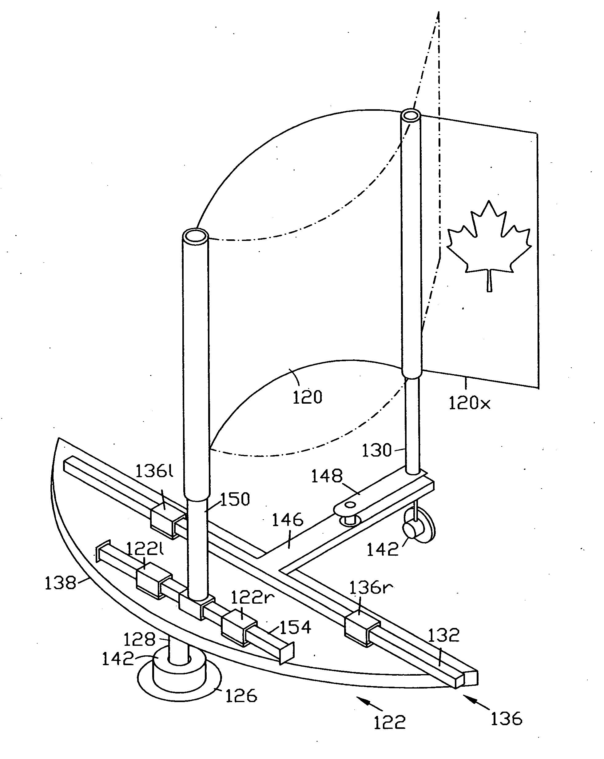
[0027]For the sake of simplicity and clarity, the concept embodied in FIG. 1 will now be described in terms of the mechanical equivalents afforded by selected combinations of moving parts, bearing in mind that these movements can occur in the same oscillation or translation cycle. For purposes of clarity and brevity, features whose function is the same or basically the same will be identified in each figure or alternative embodiment by a prefix of the figure number the variant feature appears in, followed by the feature number, the feature number being the same for all variants. Examples of embodiments making use of an oscillating foil will be described first, followed by a description of examples of embodiments making use of a translating foil.

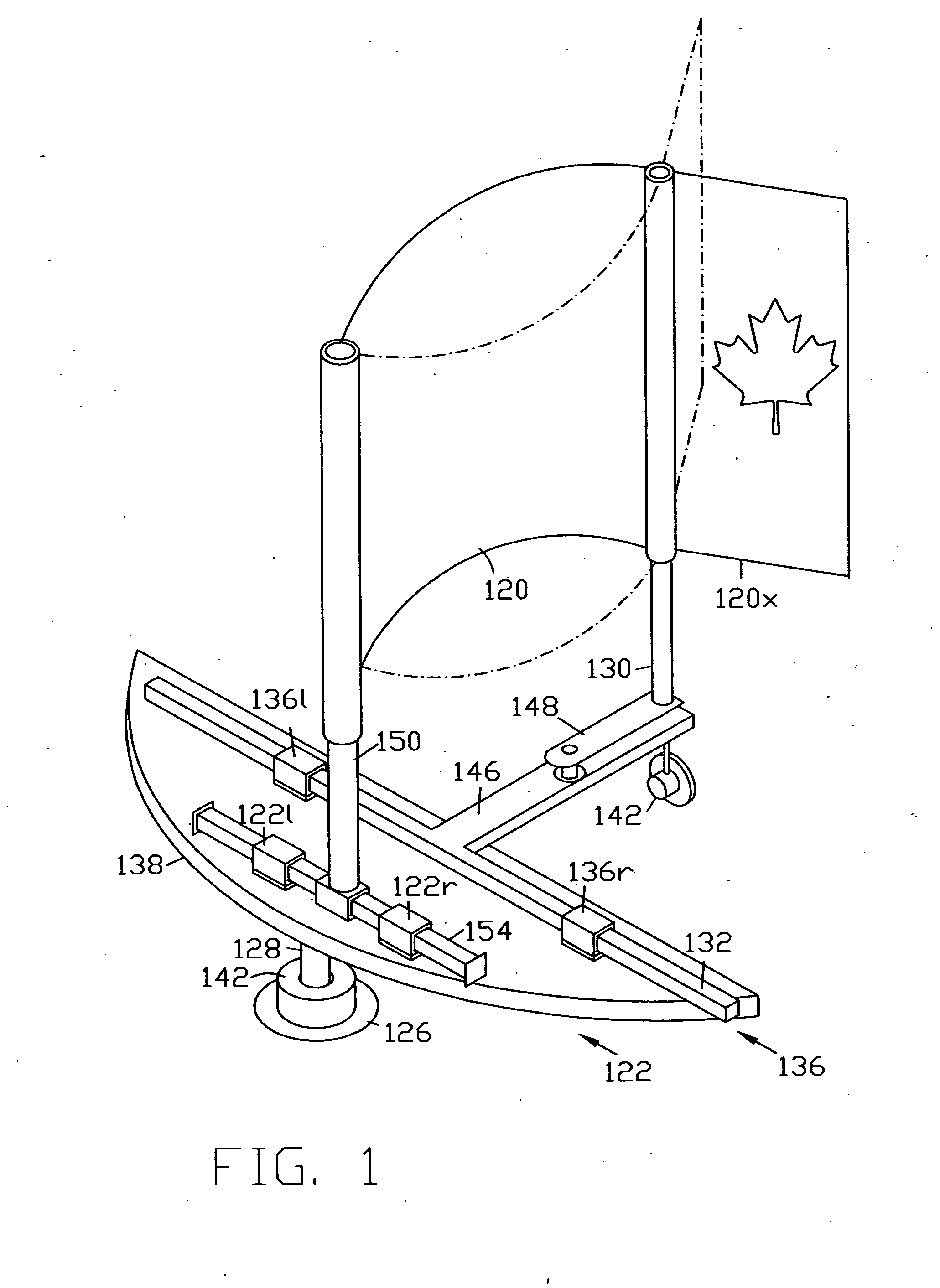
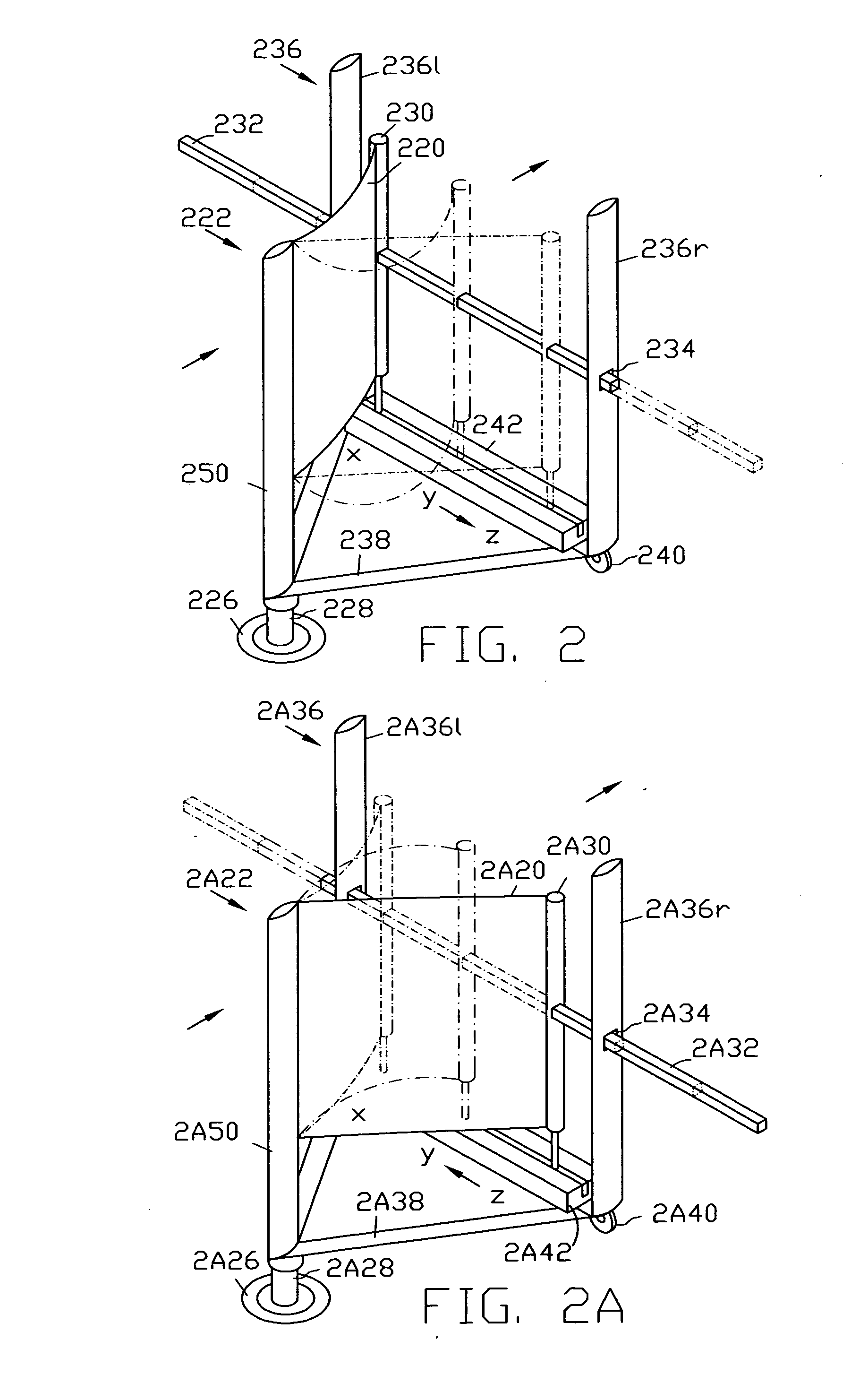
Embodiment of Oscillating Foil with Reciprocating Trailing Draft Member—FIG. 2

[0028]A variable foil 220, having a leading edge and a trailing edge, is secured at its leading edge to a leading support 222, for grounding. The leading support 22...


PUM


Abstract

The Variable Foil Machine harnesses fluid flow energy and propels fluids. A variable foil (120) with reversible camber is secured to a leading draft member (150) movable on a leading support (122) and to a trailing draft member (130) movable on a trailing support (136). The trailing draft member (130) is secured to a trailing guide (132) via a crank arm (148). Apparatus can be installed on the ground or on a pivoting base (138). In one embodiment, the leading draft member (150) is fixed while the trailing draft member (130) oscillates. In another embodiment, an oscillation amplitude offset between leading draft member (150) and trailing draft member (130) promotes cyclic translation of the variable foil (120). An energy converter (142) may be cooperatively coupled to produce energy or perform work. Selective combination of moving parts provides a versatile choice of modes of operation for power generation, work and communication.

Description

1. TECHNICAL FIELD[0001]The Variable Foil Machine relates to wings and sails and, more particularly, to oscillating wing devices that interconvert fluid flow and work or energy.2. BACKGROUND ART[0002]For centuries man has endeavored to harness the power of moving fluids to lessen his burden and explore new territories. From mills powered by water flow or wind to sail boats, ingenious means of harvesting and converting the energy of moving fluids have been devised. From simple baffle vanes to sophisticated sails and foils the efficiency of energy harvest has increased over the years. Ecological and economic considerations have, in recent years, brought a more focused attention on renewable energy as provided for example by wind and water flow. Design, for harvesting this energy, has concentrated primarily on rotary turbines, the mainstay of hydroelectric and wind for work or power generation. The low density of air necessitates the use of large turbine blades and rotors in utility wi...

Claims


Application Information

Patent Timeline
IPC IPC(8): F03D9/00F01D23/00F03D5/06
CPCF03D9/002F01D23/00F03D5/06B63H1/36B63H13/00F05B2210/16F05B2220/25F05B2240/931F05B2240/94Y02E10/30Y02E10/70Y02T70/5236Y02E10/72
Inventor KASSIANOFF, EDOUARD P.
Owner HANS DWAYNE CARTOUCHE JR MR
Why Eureka
Try Eureka