Image shake correction apparatus, and optical equipment and imaging device provided with same

Active Publication Date: 2014-04-10
CANON KK
View PDF2 Cites 4 Cited by
  • Summary
  • Abstract
  • Description
  • Claims
  • Application Information

AI Technical Summary

Benefits of technology

[0008]The present invention provides an image shake correction apparatus which prevents twisting and reduced motor efficiency, and

Problems solved by technology

Therefore, it is difficult to increase the movable range of the movable member.
However, with this image shake correction apparatus, when one of the voice coil motors is driven, the relative position of

Method used


Image

  • Image shake correction apparatus, and optical equipment and imaging device provided with same
  • Image shake correction apparatus, and optical equipment and imaging device provided with same
  • Image shake correction apparatus, and optical equipment and imaging device provided with same

Examples


Example

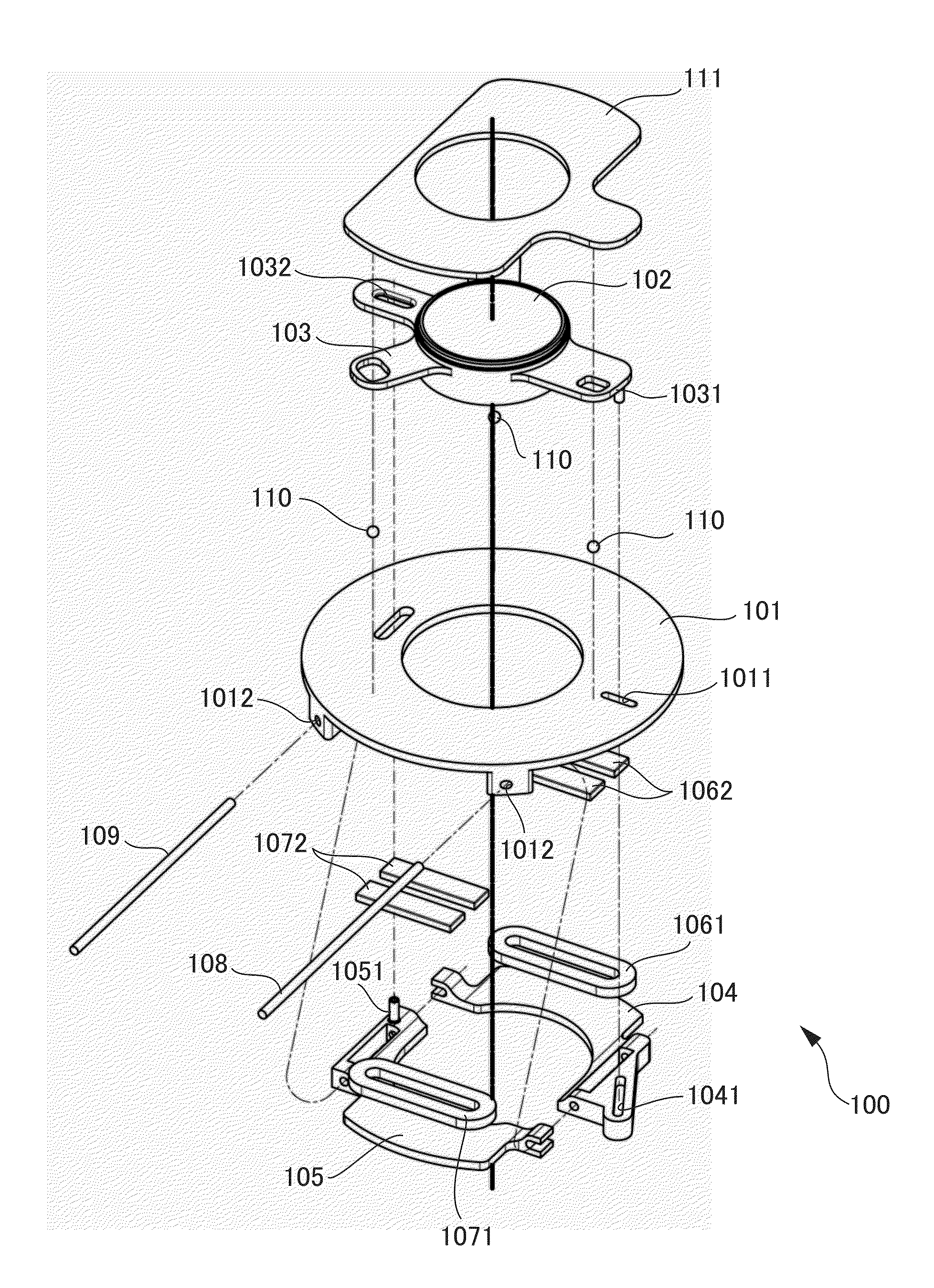
[0030]A description is now given of an image shake correction apparatus of first embodiment of the present invention with reference to FIGS. 1 to 6. The image shake correction apparatus of the present embodiment is incorporated into imaging devices such as digital cameras or digital video cameras, or optical equipment such as interchangeable lenses of single-lens reflex cameras, lens barrel units, binoculars, and telescopes (the same applies to the other embodiments described below).

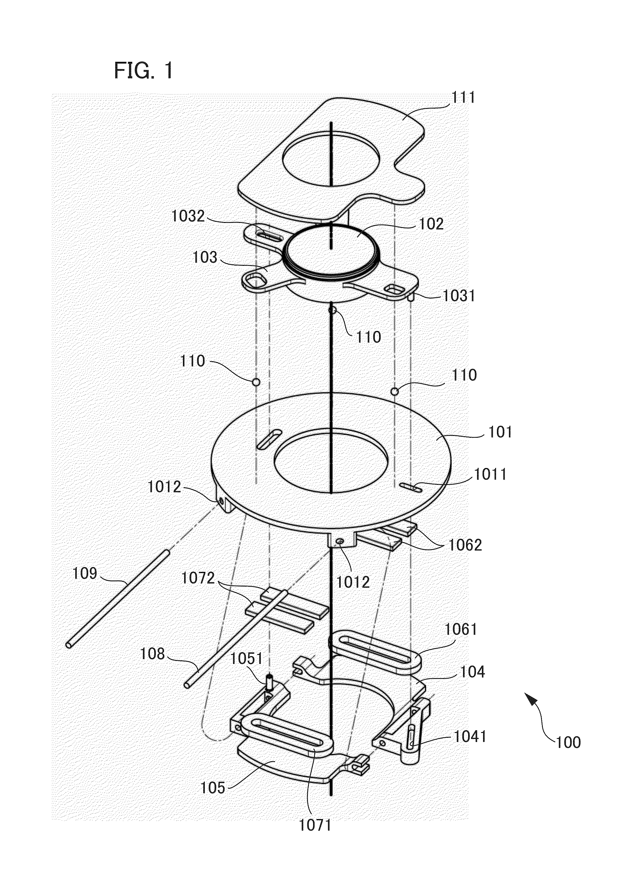
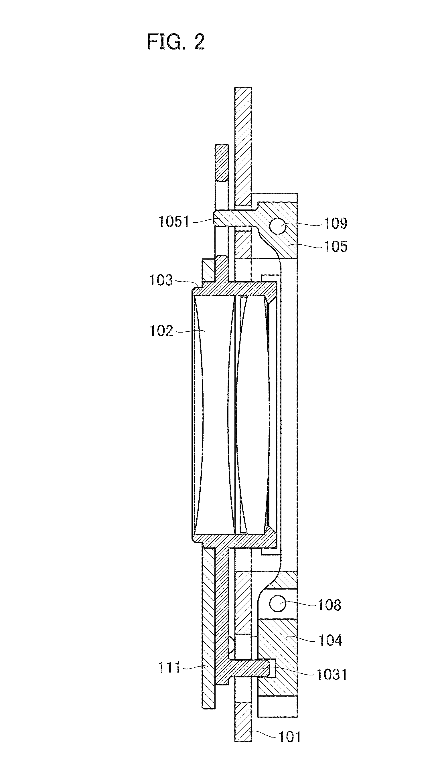
[0031]Firstly, a description is given of components configuring the image shake correction apparatus of the present embodiment using FIGS. 1 to 4. FIG. 1 is an exploded perspective view illustrating a configuration of components of an image shake correction apparatus. FIG. 2 is a cross-sectional view of the image shake correction apparatus after assembly in a plane parallel to the optical axis. FIG. 3 is a cross-sectional view in a plane that parallels the optical axis and that is perpendicular to the cr...

Example

Second Embodiment

[0072]Next, an image shake correction apparatus of second embodiment is described with reference to FIGS. 7 to 9. Components of the image shake correction apparatus of second embodiment that are identical to the components of the image shake correction apparatus 100 of first embodiment are assigned the same code numbers, and description thereof is omitted.

[0073]FIG. 7 is an exploded perspective view illustrating a component configuration of an image shake correction apparatus 200 presented in the present embodiment. FIG. 8 is a cross-sectional view in a plane parallel to the optical axis of the image shake correction apparatus after assembly.

[0074]The image shake correction apparatus 200 of second embodiment is provided with a fixed ground plate 201, the image shake correcting lens 102, the lens holding member 103, a first moving member 204, a second moving member 205, a first drive unit 206, and a second drive unit 207.

[0075]The fixed ground plate 201 is formed in ...

Example

Third Embodiment

[0090]Next, an image shake correction apparatus of third embodiment is described with reference to FIGS. 10 to 12. Components of the image shake correction apparatus of third embodiment that are identical to the components of the image shake correction apparatus of first embodiment and second embodiment are assigned the same code numbers, and description thereof is omitted.

[0091]An image shake correction apparatus 300 of third embodiment is provided with a fixed ground plate 301, the image shake correcting lens 102, a lens holding member 303, a first moving member 304, a second moving member 305, the first drive unit 206, the second drive unit 207, and a first deceleration gear 308. The image shake correction apparatus 300 is also provided with a second deceleration gear 309, a biasing spring 310, and a cover 311.

[0092]FIG. 10 is an exploded perspective view illustrating a component configuration of the image shake correction apparatus of third embodiment. FIG. 11 is...


PUM


Abstract

An image shake correction apparatus includes a fixed member; a movable member configured to hold a correcting member that corrects image shake and configured to have a first connecting unit and a second connecting unit; a first moving member connected to the first connecting unit, and configured to move the movable member in a first direction via the first connecting unit; a second moving member connected to the second connecting unit, and configured to move the movable member in a second direction different from the first direction via the second connecting unit; a first drive unit configured to drive the first moving member; and a second drive unit configured to drive the second moving member independently of driving of the first moving member. The first drive unit and the second drive unit share a constituent component.

Description

BACKGROUND OF THE INVENTION[0001]1. Field of the Invention[0002]The present invention relates to an image shake correction apparatus, and to optical equipment and imaging devices provided therewith.[0003]2. Description of the Related Art[0004]Image shake correction apparatuses have been proposed which are incorporated into imaging devices such as digital cameras for purposes of correcting image shake due to device shake of an imaging device. An image shake correction apparatus has, for example, a function which rotates as necessary a movable member that holds a lens or an imaging element in a lateral direction (yaw direction) and a vertical direction (pitch direction) viewed from an optical axis direction, and which conducts drive control in a plane that is perpendicular to the optical axis.[0005]Now, an image shake correction apparatus has been proposed wherein the movable member is directed by a guide shaft and a guide groove provided in the movable member and a fixed member, and ...

Claims


Application Information

Patent Timeline
IPC IPC(8): G02B27/64
CPCG02B27/646G03B5/02
Inventor YASUDA, HIROMU
Owner CANON KK
Why Eureka
Try Eureka