Reluctance motor with improved stator structure

a technology of stator structure and resistance motor, which is applied in the direction of motor/generator/converter stopper, dynamo-electric converter control, etc., can solve the problem of peak torque, teeth, and insufficient utilization of torque, so as to reduce the efficiency of motor and reduce the cost of control device. , the effect of reducing the efficiency of the inverter

Inactive Publication Date: 2010-05-20
DENSO CORP
View PDF25 Cites 167 Cited by
  • Summary
  • Abstract
  • Description
  • Claims
  • Application Information

AI Technical Summary

Benefits of technology

[0055]In particular, in an operating range during a permanent magnet brushless motor being rotated together with its output shaft so that no torque is required, the iron loss is mostly attributable to drag torque. That is, in the operating range, the magnetic field based on the permanent magnet of a permanent magnet brushless motor may become a problem to reduce the motor efficiency.
[0056]The structure of the control device of the permanent magnet brushless motor illustrated in FIG. 123 requires many power transistors; this increases the cost of the control device. Because a pair of power transistors are connected to each other in series for power supply to each phase stator winding, the inverter efficiency may be reduced due to the turn-on power loss of the pair of series-connected power transistors for each phase stator winding.

Problems solved by technology

Thus, the permanent magnet brushless motor illustrated in FIG. 121 may have a problem that the maximum flux density Bmax of 2.0 [T], which is fully obtained at the teeth, cannot be sufficiently utilized.
Particularly, in view of a smaller size, peak torque, which is one of the important characteristics of the permanent magnet brushless motor, may be insufficient for the same reason as the maximum flux density Bmax.
In the structure of the stator of the permanent magnet brushless motor illustrated in FIG. 121, because each of the three-phase stator windings is designed to be a distributed, full pitch winding, the arrangement of the individual three-phase windings is complicated.
This may make it difficult to produce the stator coil.
This may make it difficult to form turns of wires as the three-phase windings in corresponding slots, thus reducing the lamination factor of the stator coil.
This may reduce a torque to be created by the permanent magnet brushless motor.

Method used


Image

  • Reluctance motor with improved stator structure
  • Reluctance motor with improved stator structure
  • Reluctance motor with improved stator structure

Examples


first embodiment

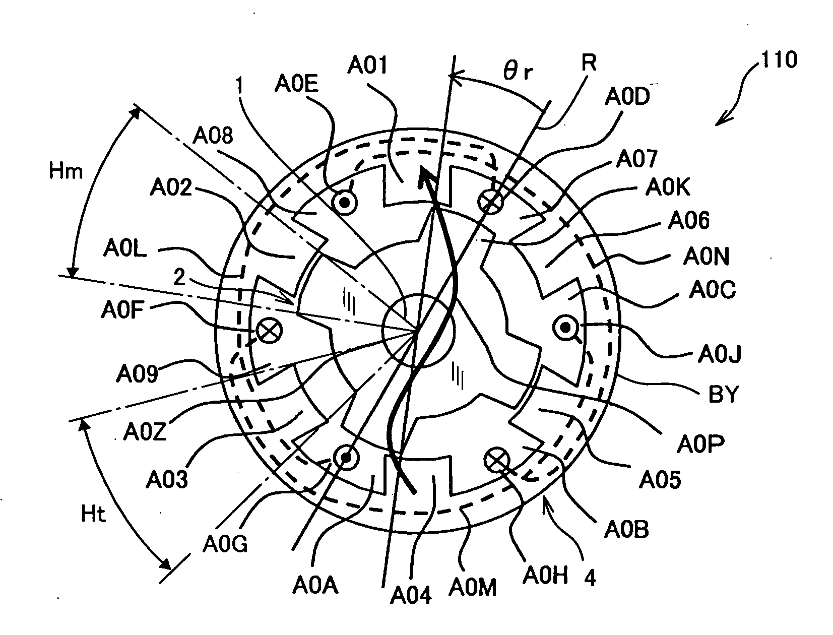
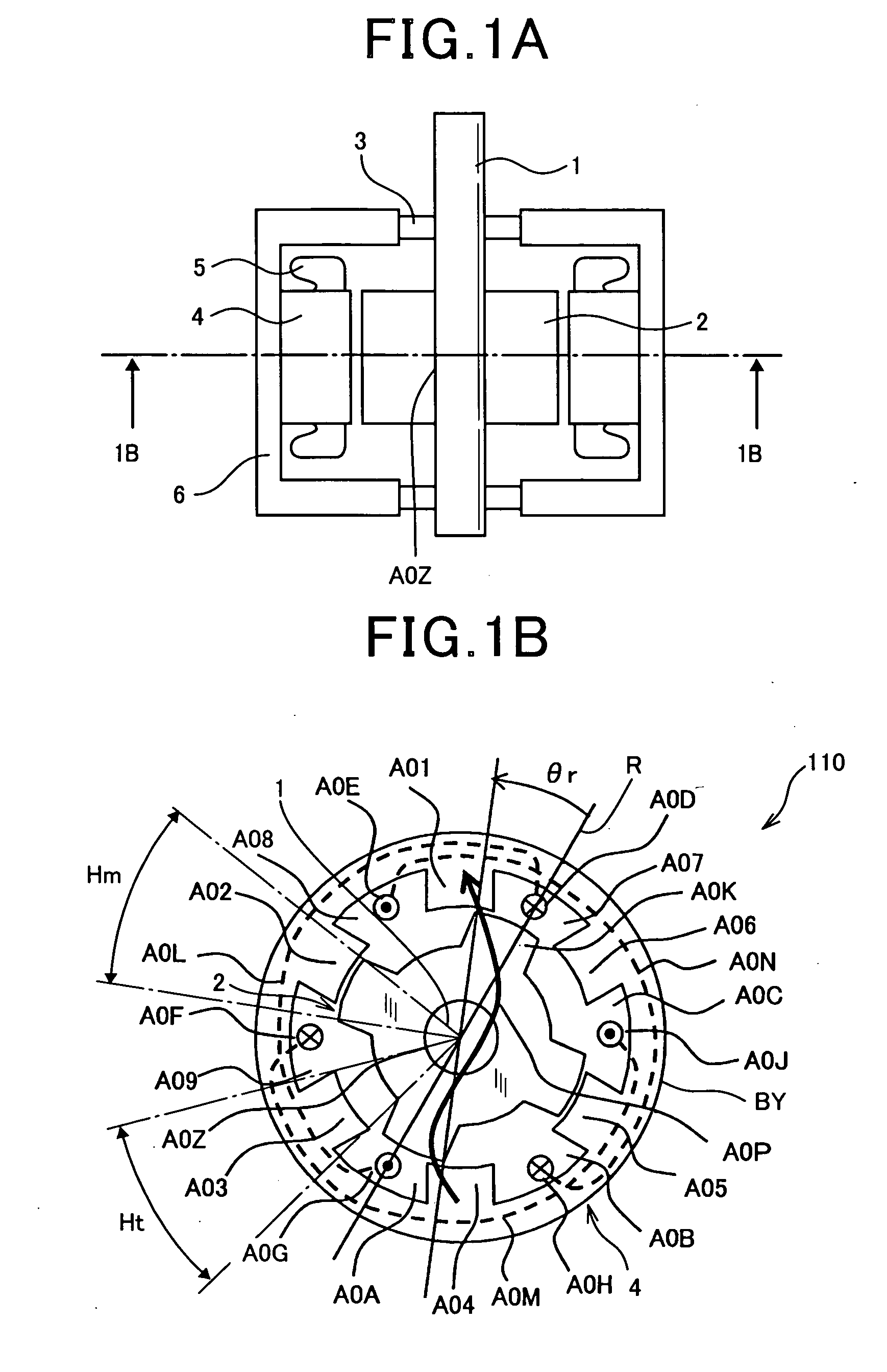
[0198]Referring to the drawings, in which like reference characters refer to like parts in several figures, there is illustrated a synchronous reluctance motor 110.

[0199]The motor 110 illustrated in FIGS. 1A and 1B is provided with an output shaft 1 and a four salient pole rotor (movable member) 2. The motor 110 is also provided with a pair of bearings 3, a substantially annular stator core 4, and a substantially cylindrical inner hollow motor housing 6 with an opening in its axial direction.

[0200]The four salient pole rotor, referred to simply as “rotor”, 2 has a substantially annular shape and a through hole A0Z at its center portion in its axial direction. The rotor 2 is coaxially is installed in the motor housing 6. An axis passing the center portion of the rotor 2 in the axial direction thereof will be referred to as “center axis” hereinafter.

[0201]The output shaft 1 is fixedly mounted on the inner surface of the through hole A0Z of the rotor 2. The output shaft 1 is disposed i...

second embodiment

[1776]A reluctance motor according to the second embodiment of the present invention will be described hereinafter with reference to FIGS. 103 and 104.

[1777]Like elements between the reluctance motor 110A and the reluctance motor 770 according to the second embodiment, to which like reference characters are assigned, are omitted or simplified in description.

[1778](a), (b), (c), and (d) of FIG. 103 schematically illustrate an example of the structure of the reluctance motor 770 according to the second embodiment of the present invention.

[1779]In comparison to the structure of the motor 1 WA illustrated in FIG. 9, the reluctance motor consists of the stator 11F and a rotor J61.

[1780]The rotor J61 is designed as a two-salient pole rotor as well as the rotor 11E.

[1781]The different point between the rotor J61 and the rotor 11E is that the circumferential electrical angular width Hm of each of the salient poles of the rotor J61 is set to 75 electrical degrees. Note that the circumferenti...

third embodiment

[1809]A reluctance motor according to the third embodiment of the present invention will be described hereinafter with reference to FIGS. 105 and 106.

[1810]Like elements between the reluctance motor 110 and the reluctance motor 780 according to the third embodiment, to which like reference characters are assigned, are omitted or simplified in description.

[1811](a), (b), (c), and (d) of FIG. 105 schematically illustrate an example of the structure of the reluctance motor 780 according to the third embodiment of the present invention.

[1812]In comparison to the structure of the motor 110 illustrated in FIG. 1B, the reluctance motor consists of the stator 4 and a rotor 2X.

[1813]The rotor 2X is designed as a four-salient pole rotor as well as the rotor 2.

[1814]The different point between the rotor 2X and the rotor 2 is that the circumferential electrical angular width Hm of each of the salient poles of the rotor 2X is set to 45 electrical degrees.

[1815]A control device, such as control d...


PUM


Abstract

In a motor, a stationary member is provided with a number M (M is a positive integer) of first poles within 360 electrical degrees at spaces therebetween. A plurality of windings are at least partly wound in the spaces, respectively. A movable member is movably arranged relative to the stationary member and provided with a number K (K is a positive integer) of second poles. The number K of second poles is different from the number M of first poles. A unidirectional current supply unit supplies a unidirectional current to at least one of the windings so as to create an attractive force between at least one of the first poles and a corresponding at least one of the second poles to thereby move the movable member relative to the stationary member.

Description

CROSS REFERENCE TO RELATED APPLICATIONS[0001]This application is based on Japanese Patent Applications No. 2008-292142 and No. 2009-119063 filed on Nov. 14, 2008 and May 15, 2009, respectively. This application claims the benefit of priority from the Japanese Patent Applications, so that the descriptions of which are all incorporated herein by reference.FIELD OF THE INVENTION[0002]The present invention relates to reluctance motors installable in various motor vehicles, such as passenger cars and trucks, various types of industrial equipment, and various home appliances, and to systems including such motors and circuits for driving the motors.BACKGROUND OF THE INVENTION[0003]Three-phase AC (Alternating Current) motors have been widely used, an example of which is disclosed in Japanese Patent Application Publication No. 2005-110431.[0004]FIG. 120 is an axial cross sectional view illustrating a schematic structure of a surface permanent magnet synchronous motor as an example of such th...

Claims


Application Information

Patent Timeline
Patent Type & Authority Applications(United States)
IPC IPC(8): H02P6/08H02K37/04
CPCH02K1/12H02K1/146H02K1/165H02K1/246H02K1/276H02K3/28H02P25/085H02K16/02H02K21/14H02K21/44H02K41/03H02K2201/18H02K3/345H02P25/092
Inventor NASHIKI, MASAYUKIISHIKAWA, TOMOKAZUITO, YUICHIRO
Owner DENSO CORP
Why Eureka
Try Eureka