Infusion pump

a technology of infusion pump and pump body, which is applied in the direction of positive displacement liquid engine, process and machine control, instruments, etc., can solve the problems of excessive amount of liquid being administered to patients, the pump poses a risk of “free flow”, and the liquid falling under gravity

Active Publication Date: 2014-04-10
NIPRO CORP
View PDF2 Cites 54 Cited by
  • Summary
  • Abstract
  • Description
  • Claims
  • Application Information

AI Technical Summary

Benefits of technology

[0027]The present invention can reliably prevent free flow due to operational errors by health-care professionals such as nurses or due to some other causes.

Problems solved by technology

Infusion treatment using such an infusion pump poses a risk of “free flow”.
Free flow, an incident that infusion liquid falls under gravity and is administered to a patient in an excessive amount, may occur when an infusion tube is removed from the infusion pump or in other occasions.

Method used


Image

  • Infusion pump
  • Infusion pump
  • Infusion pump

Examples


embodiment 1-1

Infusion Pump

[0095]An example of an infusion pump according to the present invention is described with reference to FIG. 1 to FIG. 15.

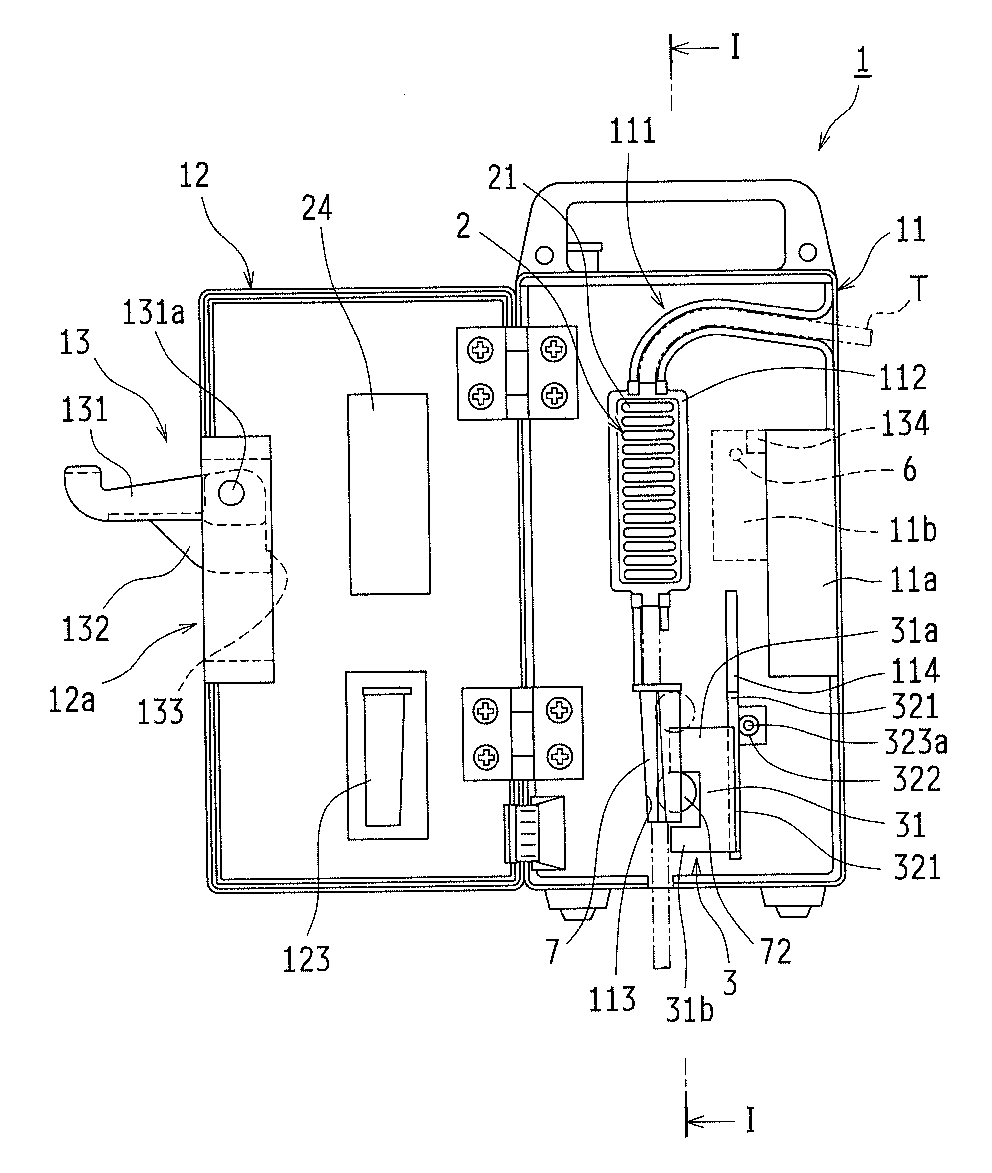
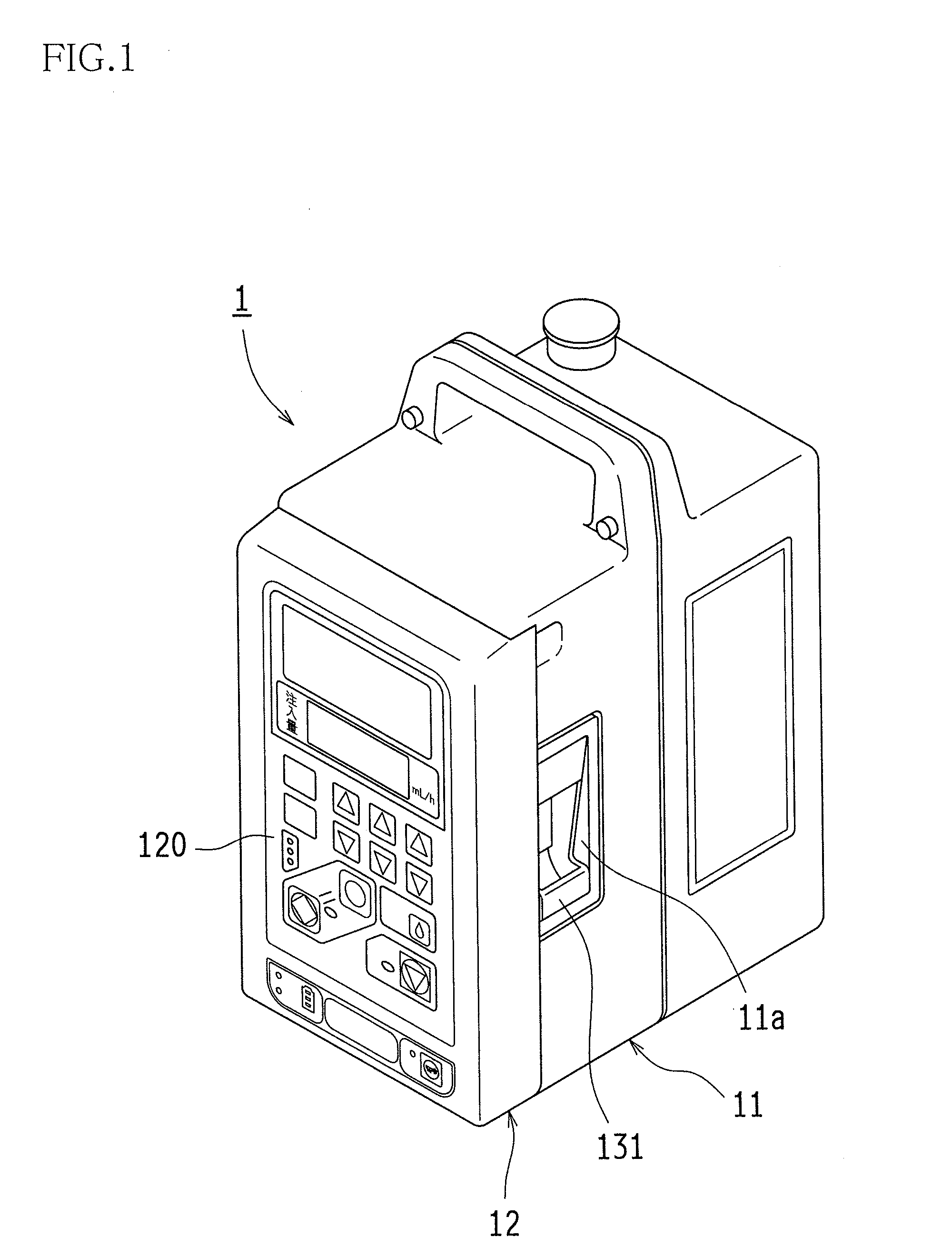
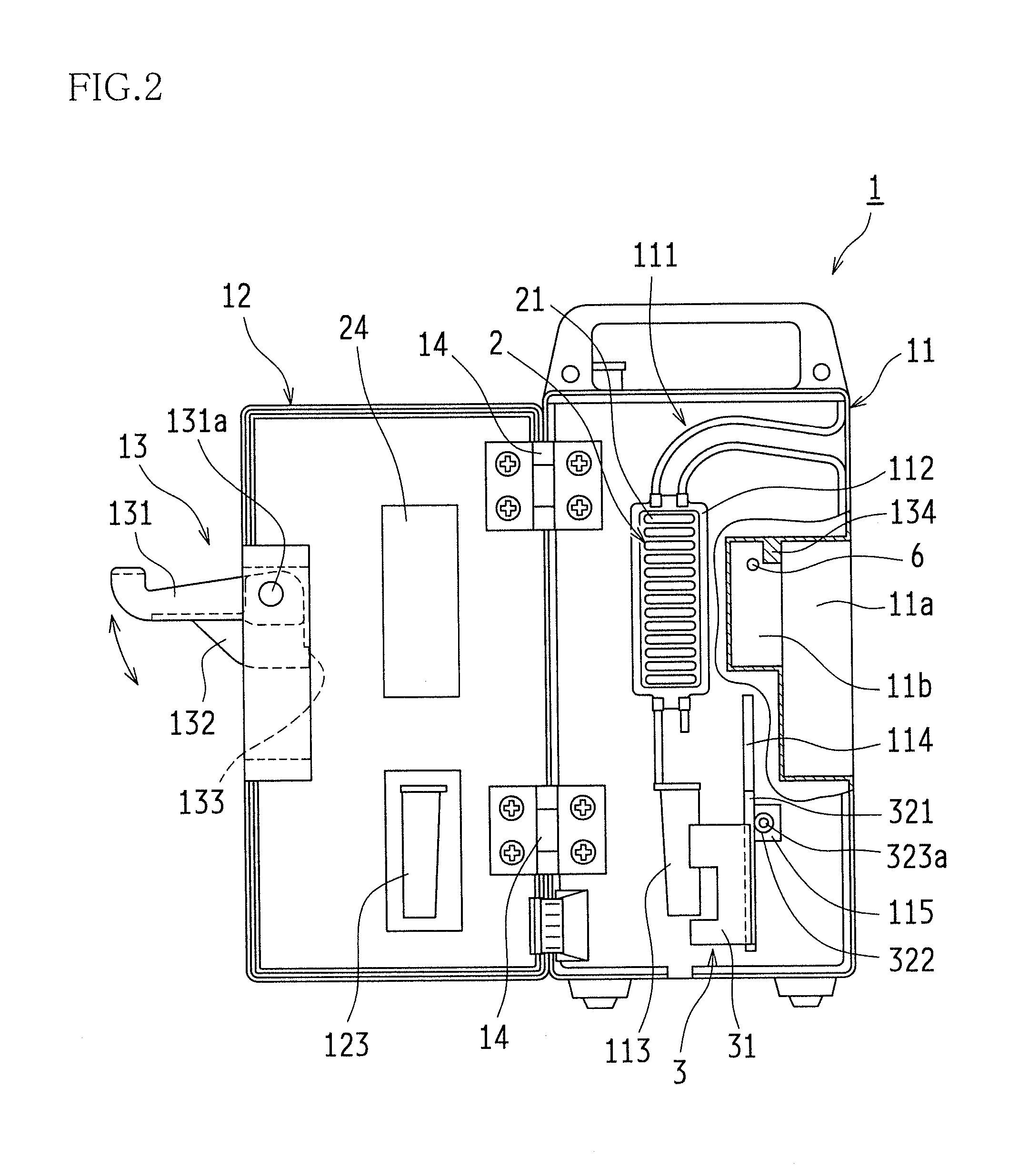
[0096]An infusion pump 1 in this example is a peristaltic finger infusion pump, and is equipped with a pump body (a casing) 11, and a door 12 which closes on a front face (a tube attachment position) of the pump body 11. The door 12 is held swingably (in a freely turning manner) on the pump body 11 by hinges 14, 14, and is capable of swinging between a fully closed position and a fully open position (for example, a 180-degree open position) with respect to the front face of the pump body 11.

[0097]At the front face of the pump body 11, there are provided a tube attachment guide 111, a pump unit 112 which is connected to the tube attachment guide 111 and which has an enlarged rectangular shape, and a clamp holding recess 113, in this order from the upstream side in an infusion liquid feed direction. The groove width of the tube attachment guide 111 corr...

embodiment 1-2

[0137]Hereinafter, another example of the roller movement mechanism is described with reference to FIG. 16. FIG. 16 shows only the roller slider 301 and omits other components of the roller movement mechanism. Except the arrangements to be described below, [Embodiment 1-2] is similar to [Embodiment 1-1], and hence detailed description of similar elements is omitted.

[0138]The roller slider 301 in this example is characterized in that the distance D between the block-side pushing piece 301a and the release-side pushing piece 301b is greater than the length L of the clamp body 71 of the roller clamp 7.

[0139]In this example, while the door 12 of the infusion pump 1 is open, the roller clamp 7 stays at an origin position as shown in FIG. 16(A). The origin position in this context means a position at which the clamp body 71 of the roller clamp 7 held in the clamp holding recess 113 (shown in FIG. 2) stays in a gap between the block-side pushing piece 301a and the release-side pushing piec...

embodiment 1-3

[0143]Another example of an infusion pump according to the present invention is described with reference to FIG. 17 to FIG. 26.

[0144]Similar to [Embodiment 1-1] described above, an infusion pump 100 in this example is a peristaltic finger infusion pump, and is equipped with a pump body (a casing) 11, and a door 12 which closes on a front face (a tube attachment position) of the pump body 11. The door 12 is swingably held on the pump body 11 by hinges 14, 14, and is capable of swinging between a fully closed position and a fully open position (for example, a 180-degree open position) with respect to the front face of the pump body 11.

[0145]Except the arrangements to be described below, the infusion pump 100 in this example is similar to the one described in [Embodiment 1-1], and hence detailed description of similar elements is omitted.

——Pump Body——

[0146]Also in this example, the pump body 11 is provided with a tube attachment guide 111 and a pump unit 112 at a substantially central ...


PUM


Abstract

An infusion pump includes a pump body for holding a roller clamp 7, and a roller movement mechanism 3 for moving a roller 72 of the roller clamp 7 and operating in coordination with manipulation of a door lock mechanism. When the door lock mechanism is in an unlocked state, an infusion tube T is blocked by the roller clamp 72. This configuration reliably prevents free flow even if a door is not closed completely or if the door is accidentally left unlocked. After the finish of infusion treatment, the infusion tube T is blocked by the roller clamp 7 at the moment when the door lock mechanism is unlocked before the opening of the door. This configuration avoids a trouble of removing the infusion tube T from the infusion pump while a user forgets to block the infusion tube by the roller clamp 7.

Description

FIELD OF THE INVENTION[0001]The present invention relates to infusion pumps.BACKGROUND ART[0002]As infusion pumps employed to infuse medical drug solution into a patient's body, various types of infusion pumps are known, including mechanical infusion pumps, gravity infusion pumps which entirely depend on gravity, and precompression-type infusion pumps.[0003]Mechanical infusion pumps include syringe infusion pumps in which a piston of a syringe is pressed to feed infusion liquid, and peristaltic infusion pumps. Peristaltic infusion pumps include roller infusion pumps in which an infusion tube is pressed by a roller-equipped rotor or the like to feed infusion liquid, and finger infusion pumps.[0004]Among these infusion pumps, a peristaltic finger infusion pump is equipped with a pump mechanism having, for example, a plurality of fingers aligned in one direction (along an infusion tube), cams for advancing and retracting the fingers independently, a door of the pump, and a pressing pla...

Claims


Application Information

Patent Timeline
Patent Type & Authority Applications(United States)
IPC IPC(8): A61M5/168A61M5/142
CPCA61M5/142A61M5/16813F04B43/0081F04B43/082F04B43/1223F04B49/10A61M39/286A61M5/14228A61M39/281A61M39/285A61M2205/14
Inventor UEDA, MITSUTAKAAKAI, RYOICHITAKAHASHI, HIDENORI
Owner NIPRO CORP
Why Eureka
Try Eureka