Hot melt systems, feeder devices and methods for moving particulate hot melt adhesive

a technology of hot melt adhesive and feeder device, which is applied in the direction of film/foil adhesives, coatings, transportation and packaging, etc., can solve the problems of premature heating or melting of hot melt adhesive before it reaches the limit relative of the pneumatic feed system, interference with the proper transfer of hot melt adhesive, etc., and achieves less maintenance and less downtime

Active Publication Date: 2014-04-17
NORDSON CORP
View PDF23 Cites 17 Cited by
  • Summary
  • Abstract
  • Description
  • Claims
  • Application Information

AI Technical Summary

Benefits of technology

[0013]Hot melt adhesive systems, feeder devices and methods according to the present invention provide several advantages. For one, particulate hot melt adhesive can be reliably moved between an adhesive supply and an adhesive melter. In addition, the feeder devices are effective for moving particulate hot melt adhesives of varying sizes. Furthermore, the feeder devices provide a physical, thermal separation between an adhesive melter and an adhesive supply, such as by offsetting the adhesive supply from directly above the heating elements in the adhesive melter. Therefore, the feeder device is less likely to become fouled up than previous arrangements which transferred heat to the feeder device and caused premature heating or melting of the hot melt adhesive before it reached the melter. More generally, a self-contained hot melt adhesive system including an adhesive melter and an adhesive supply can be provided in a manner that thermally isolates the adhesive supply and the adhesive melter and allows the intermittent supply of particulate hot melt adhesive from the adhesive supply to the adhesive melter. Particulate hot melt adhesive in the hopper remains cool and unmelted, and may be fed as desired into the adhesive melter according to application needs. In addition, systems and devices employing the invention can require less maintenance and cause less downtime than previous arrangements. Moreover, the feeder devices can be integrated directly into adhesive supply and adhesive melter devices, or can be used as a separate component. In addition, a drive mechanism used with the feeder devices can both operate the mechanical agitator and move the feeder between positions.

Problems solved by technology

Particulate hot melt adhesive must be moved from the adhesive supply to the melter, and the size and shape of the particulate hot melt adhesive and the construction of the adhesive supply and the melter can present challenges that affect this movement.
However, such pneumatic feed systems have a limit relative to the size of particulate hot melt adhesive they can transfer in a cost effective manner.
Transferring heat to the lid and transfer hose can cause premature heating or melting of the hot melt adhesive before it reaches the melter.
This can cause problems such as interference with the proper transfer of hot melt adhesive into the melter.
Also, air-driven feed systems often include an air filter, which requires periodic replacement or cleaning, and therefore results in system downtime.
Furthermore, large bins used as the adhesive supply in air-driven feed systems undesirably increase the overall floor space requirements of the system.
In addition, the particulate hot melt adhesives in these large bins can become compacted and begin to stick together, forming larger clumps of particulate hot melt adhesive that are heavier and more difficult to transfer using an air-driven feed system.
Further, larger clumps of particulate hot melt adhesive can cause blockages in the transfer hose, which interfere with transferring hot melt adhesive to the melter.
Transferring heat to the hopper can cause premature heating or melting of the hot melt adhesive in the hopper, which can interfere with the efficient transfer of hot melt adhesive into the melter.
This, as well as the other issues discussed above, contributes to downtime of the hot melt adhesive system.

Method used


Image

  • Hot melt systems, feeder devices and methods for moving particulate hot melt adhesive
  • Hot melt systems, feeder devices and methods for moving particulate hot melt adhesive
  • Hot melt systems, feeder devices and methods for moving particulate hot melt adhesive

Examples


Embodiment Construction

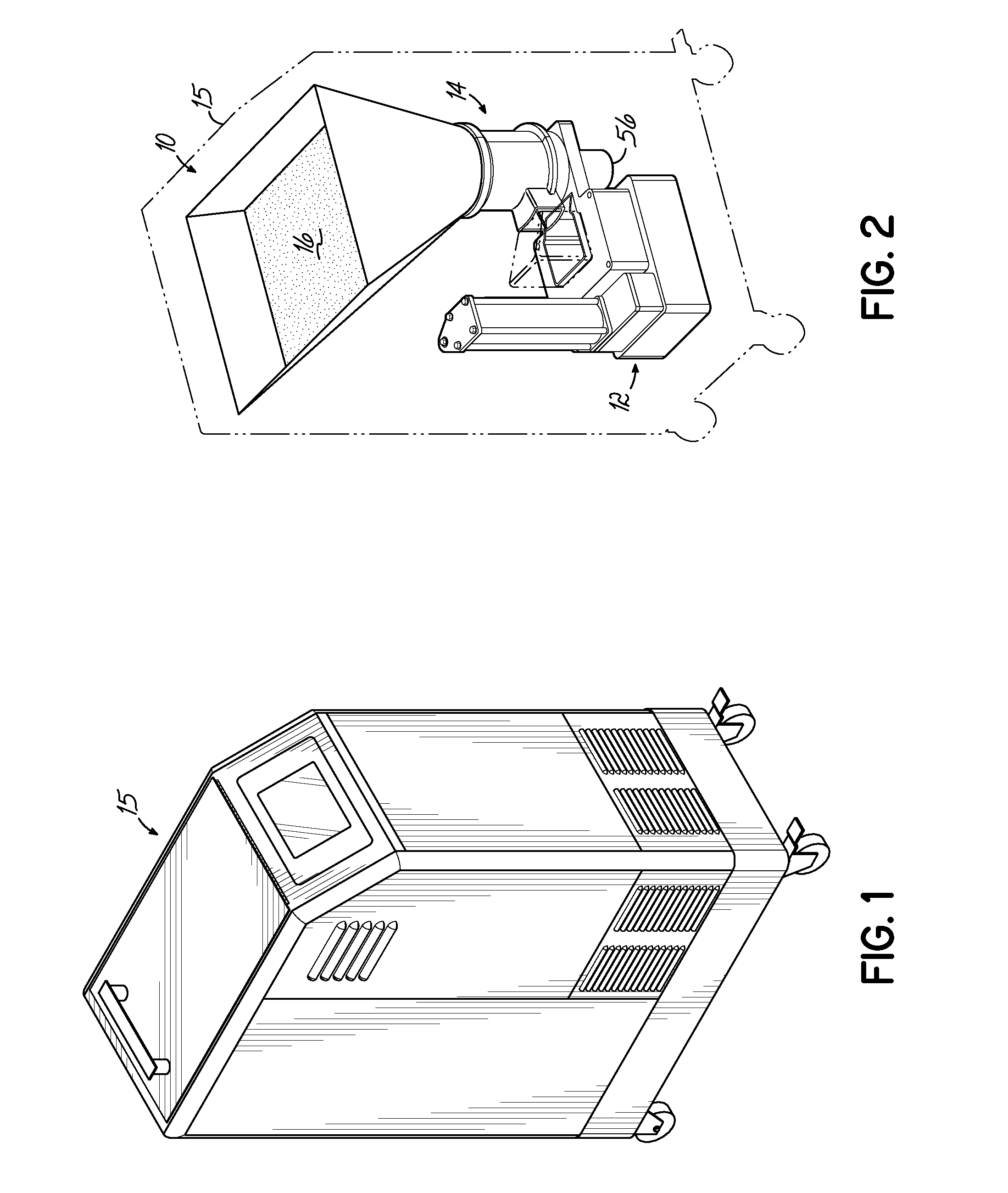
[0025]Referring first to FIGS. 1 and 2, components of an exemplary hot melt adhesive system are shown, including an adhesive supply 10 and a melter 12. A feeder device 14 is positioned generally between the adhesive supply 10 and the melter 12, and may be used to feed, or transfer, particulate hot melt adhesive 16 from the adhesive supply 10 to the melter 12. The adhesive supply 10 contains a bulk quantity of particulate hot melt adhesive 16, and can be a tank or hopper, for example. The melter 12 heats and melts the particulate hot melt adhesive 16 that is provided to the melter 12, turning it into a liquid hot melt adhesive that is directed to one or more points of application using devices and methods well known in the art.

[0026]Although FIGS. 1 and 2 depict the adhesive supply 10, the adhesive melter 12, and the feeder device 14 all contained within or connected with a single common housing structure 15, or housing, of a machine, it will be appreciated that various embodiments o...


PUM

PropertyMeasurementUnit
cylindrical shapeaaaaaaaaaa
thermalaaaaaaaaaa
meltaaaaaaaaaa

Abstract

Systems, feeder devices and methods for moving particulate hot melt adhesive from an adhesive supply to an adhesive melter. A feeder device includes a body having an inlet and an outlet, and an interior communicating with the inlet and the outlet. The inlet is configured to receive particulate hot melt adhesive from an outlet of the adhesive supply, and the outlet is configured to provide particulate hot melt adhesive to an inlet of the adhesive melter. The feeder device further includes a mechanical agitator positioned in the interior for urging the particulate hot melt adhesive in a flow direction toward the outlet.

Description

CROSS-REFERENCE TO RELATED APPLICATION[0001]This application claims the priority of Application Ser. No. 61 / 712,414 filed Oct. 11, 2012 (pending), the disclosure of which is hereby incorporated by reference herein.FIELD OF THE INVENTION[0002]The present invention generally relates to hot melt adhesive dispensing equipment, and more particularly to moving hot melt adhesive between an adhesive supply and an adhesive melter in a hot melt adhesive dispensing system.BACKGROUND[0003]Hot melt adhesive systems have many applications in manufacturing and packaging. For example, thermoplastic hot melt adhesives are used for carton sealing, case sealing, tray forming, pallet stabilization, nonwoven applications including diaper manufacturing, and many other applications. Hot melt adhesives often come in the form of pellets or particulates and are contained in or provided from an adhesive supply, such as a tank or hopper. The hot melt adhesive pellets are heated and melted by a melter, and liqu...

Claims


Application Information

Patent Timeline
Patent Type & Authority Applications(United States)
IPC IPC(8): B65G19/04C09J7/00
CPCB65G19/04B05C11/1002B05C11/1042B29B13/022B29C31/02B29C31/048B32B37/1284B32B2037/1215B65G19/14
Inventor CHAU, SING YICLARK, JUSTIN A.RIDGE, WILLIAM M.VARGA, LESLIE J.
Owner NORDSON CORP
Why Eureka
Try Eureka