Active Power Factor Corrector Circuit

a technology of active power factor and corrector circuit, which is applied in the field of circuits, can solve the problems of low power factor industrial or commercial customers, energy loss in the distribution system, and higher cost for electrical utilities

Active Publication Date: 2014-04-17
INFINEON TECH AG
View PDF6 Cites 28 Cited by
  • Summary
  • Abstract
  • Description
  • Claims
  • Application Information

AI Technical Summary

Problems solved by technology

When the power factor is low, the high current causes energy to be lost in the distribution system, requiring larger wires and other equipment capable of handling the higher current compared to a system with a higher power factor.
Because of the costs of larger equipment and wasted energy, electrical utilities will charge a higher cost to industrial or commercial customers who have a low power factor than to those who have a higher power factor.

Method used


Image

  • Active Power Factor Corrector Circuit
  • Active Power Factor Corrector Circuit
  • Active Power Factor Corrector Circuit

Examples


Embodiment Construction

[0017]The making and using of the presently preferred embodiments are discussed in detail below. It should be appreciated, however, that the present invention provides many applicable inventive concepts that can be embodied in a wide variety of specific contexts. The specific embodiments discussed are merely illustrative of specific ways to make and use the invention, and do not limit the scope of the invention.

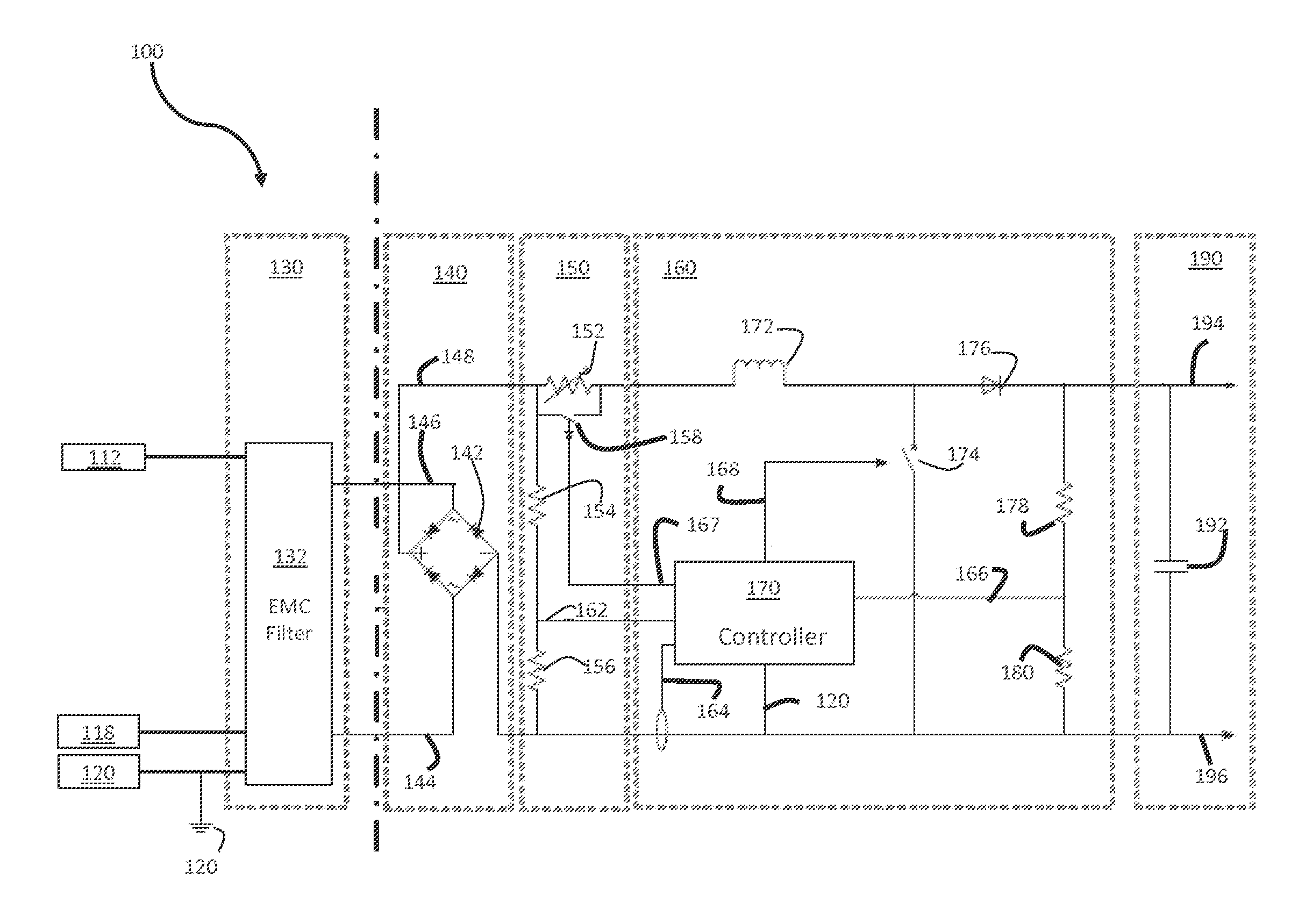
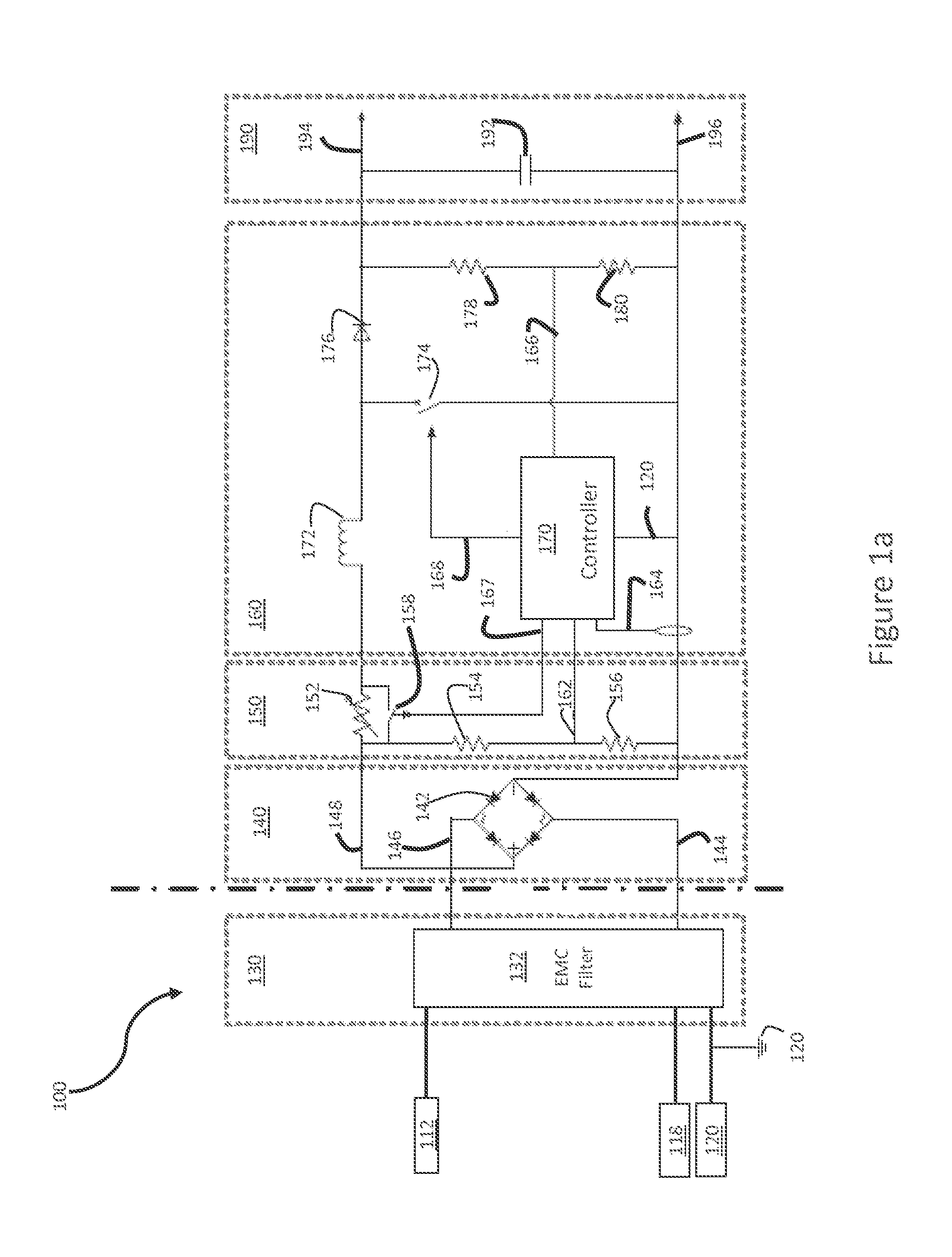
[0018]The present invention will be described with respect to preferred embodiments in a specific context, namely an active PFC circuit. The invention may also be applied, however, to other types of circuits, systems, and methods.

[0019]The power factor, a dimensionless number between zero and one, is defined as the ratio of the real power flowing to the load to the apparent power in the circuit. Real power is the capacity of the circuit to perform work at a particular time, while apparent power is the product of the current and the voltage of the circuit. Due to energy stored...


PUM


Abstract

In accordance with an embodiment, an electronic device includes a controller configured to be coupled to a first switch of a power factor corrector. The controller is configured to produce a variable switching frequency depending on a load current. For a first load current, the controller is configured to produce a first switching frequency, and for a second load current, the controller is configured to produce a second switching frequency.

Description

TECHNICAL FIELD[0001]The present invention relates to the field of circuits, in particular to active power factor corrector circuits.BACKGROUND[0002]In electronic devices, power factor corrector (PFC) circuits are increasingly used to increase the power factor (PF) of AC electric power systems. In electronic power systems, a load with a low power factor draws more current than a load with a high power factor for the same amount of useful power transferred. When the power factor is low, the high current causes energy to be lost in the distribution system, requiring larger wires and other equipment capable of handling the higher current compared to a system with a higher power factor.[0003]Because of the costs of larger equipment and wasted energy, electrical utilities will charge a higher cost to industrial or commercial customers who have a low power factor than to those who have a higher power factor. Power factor regulations are also becoming increasingly prevalent.[0004]Power fac...

Claims


Application Information

Patent Timeline
Patent Type & Authority Applications(United States)
IPC IPC(8): G05F1/70H02J7/00H02M1/00H02M1/42
CPCH02M1/4225Y02B70/10H02M1/0032H02J7/00H02M1/42H02M3/158
Inventor CARLETTI, ANDREAPIDUTTI, ALBINO
Owner INFINEON TECH AG
Why Eureka
Try Eureka