Power factor correction (PFC) controller and bridgeless pfc circuit with the same

a bridgeless pfc and controller technology, applied in the field of power factor correction (pfc) controller and application circuit with the same, can solve the problems of affecting the overall conversion efficiency of the power conversion unit, the inability to detect the current state of the switching unit and the current current of the inductor, and the inability to properly control the switching unit swb>1/b>, swb>2/b>, swb>3

Inactive Publication Date: 2013-09-26
NIKO SEMICON
View PDF7 Cites 22 Cited by
  • Summary
  • Abstract
  • Description
  • Claims
  • Application Information

AI Technical Summary

Benefits of technology

[0016]It is another object of the present invention to provide a PFC controller, which is able to detect conductive current of the switching unit on matter during the positive half cycles or the negative half cycles of the output from the ac power source.

Problems solved by technology

Environmental protection and power conservation has become an important issue nowadays.
Conduction loss from the diodes may affect overall conversion efficiency.
Thus, the difficulty for detecting inductor current and current state of the switching unit to properly control the switching units sw1, sw2, sw3, and sw4 is unpreventable.

Method used


Image

  • Power factor correction (PFC) controller and bridgeless pfc circuit with the same
  • Power factor correction (PFC) controller and bridgeless pfc circuit with the same
  • Power factor correction (PFC) controller and bridgeless pfc circuit with the same

Examples


Embodiment Construction

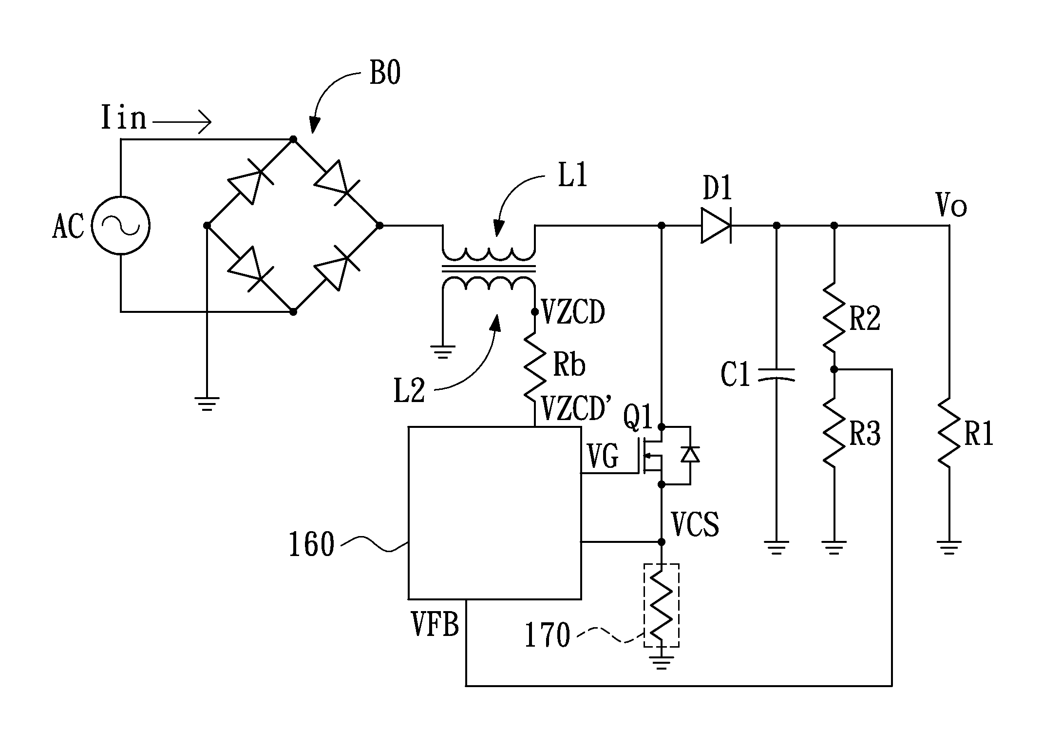
[0031]FIG. 4 is a schematic view showing an application circuit for a power factor correction (PFC) controller in accordance with an embodiment of the present invention. As shown, the application circuit includes a bridge rectifier circuit B0 and a DC-to-DC converter circuit. The voltage input from the ac power source is first converted to a DC output by the bridge rectifier circuit B0, and then the DC output is converted into the output voltage Vo by the DC-to-DC converter circuit supplied to the load R1.

[0032]The DC-to-DC converter circuit includes an inductor L1, a switching unit Q1, a diode D1, a capacitor C1, a switching unit current detector 170, an auxiliary inductor L2, a voltage divider composed of resistors R2 and R3, and a PFC controller 160. The switching unit current detector 170 includes a resistor serially connected to the switching unit Q1 for detecting the conductive current flowing through the switching unit Q1 so as to generate a conductive-current detecting signa...


PUM


Abstract

A power factor correction (PFC) controller for controlling at least a switching unit is provided. The PFC controller has a feedback control circuit, a conductive current detecting circuit, and a switching control circuit. The feedback control circuit generates a feedback control signal for turning off the switch according to a feedback voltage signal. The conductive current detecting circuit has a clamp circuit, which generates a clamped signal restricted in a positive potential varying range according to a negative potential portion of a conductive-current detecting signal, and generates a cutoff signal for turning off the switch according to at least the clamped signal. The switching control circuit is utilized for controlling the switch according to the feedback control signal and the cutoff signal.

Description

BACKGROUND OF THE INVENTION[0001](1) Field of the Invention[0002]This invention relates to a power factor correction (PFC) controller and application circuits with the same, and particularly relates to a PFC controller for a bridgeless PFC circuit.[0003](2) Description of the Prior Art[0004]Environmental protection and power conservation has become an important issue nowadays. The trend of improving power efficiency of isolated ac power suppliers is directed to the development of topologies of secondary side synchronous rectifier control and primary side power factor correction (PFC) control.[0005]FIGS. 1A and 1B are schematic views showing a typical full-bridge PFC application circuit. As shown, the application circuit includes a bridge rectifier circuit and a DC-to-DC convertor. Power provided by the ac power source is converted into DC power first and then converted by the DC-to-DC converter to generate the output voltage Vo for driving the load Ro.[0006]As shown, during the posi...

Claims


Application Information

Patent Timeline
Patent Type & Authority Applications(United States)
IPC IPC(8): G05F1/70
CPCH02M1/4225Y02B70/126H02M1/4233Y02B70/10H02M1/0085
Inventor HSU, TA-CHING
Owner NIKO SEMICON
Why Eureka
Try Eureka