Gas concentration detection device

a detection device and gas concentration technology, applied in measurement devices, scientific instruments, instruments, etc., can solve the problems of inevitable deterioration of exhaust emission, reduce gas sensitivity, reduce detection current of deteriorated cells, and reduce the deterioration of that cell

Active Publication Date: 2020-02-18
DENSO CORP
View PDF19 Cites 0 Cited by
  • Summary
  • Abstract
  • Description
  • Claims
  • Application Information

AI Technical Summary

Benefits of technology

[0011]According to the present disclosure, the pump cell voltage is lowered from the target voltage and becomes the detection voltage, and thus the oxygen corresponding to the detection voltage flows from the pump cell side to the monitor cell and sensor cell sides. The residual oxygen concentration in the case of voltage application to the pump cell at the detection voltage exceeds the residual oxygen concentration in the case of voltage application to the pump cell at the target voltage. Because the currents outputted by the monitor cell and the sensor cell are currents corresponding to the residual oxygen concentration, the detection current of the deteriorated cell is lowered as a result of the deterioration when one of the monitor cell and the sensor cell deteriorates and its gas sensitivity is reduced, and thus the deterioration of that cell can be grasped. In this manner, the gas sensitivity can be determined without the concentration of the gas in the exhaust gas to be measured having to be fluctuated to a significant extent.
[0012]According to the present disclosure, the gas concentration detection device that is capable of determining a decline in gas sensitivity and requires no significant fluctuation of the concentration of a gas to be measured can be provided.

Problems solved by technology

Accordingly, exhaust emission deterioration is inevitable during deterioration determination.

Method used


Image

  • Gas concentration detection device
  • Gas concentration detection device
  • Gas concentration detection device

Examples


first embodiment

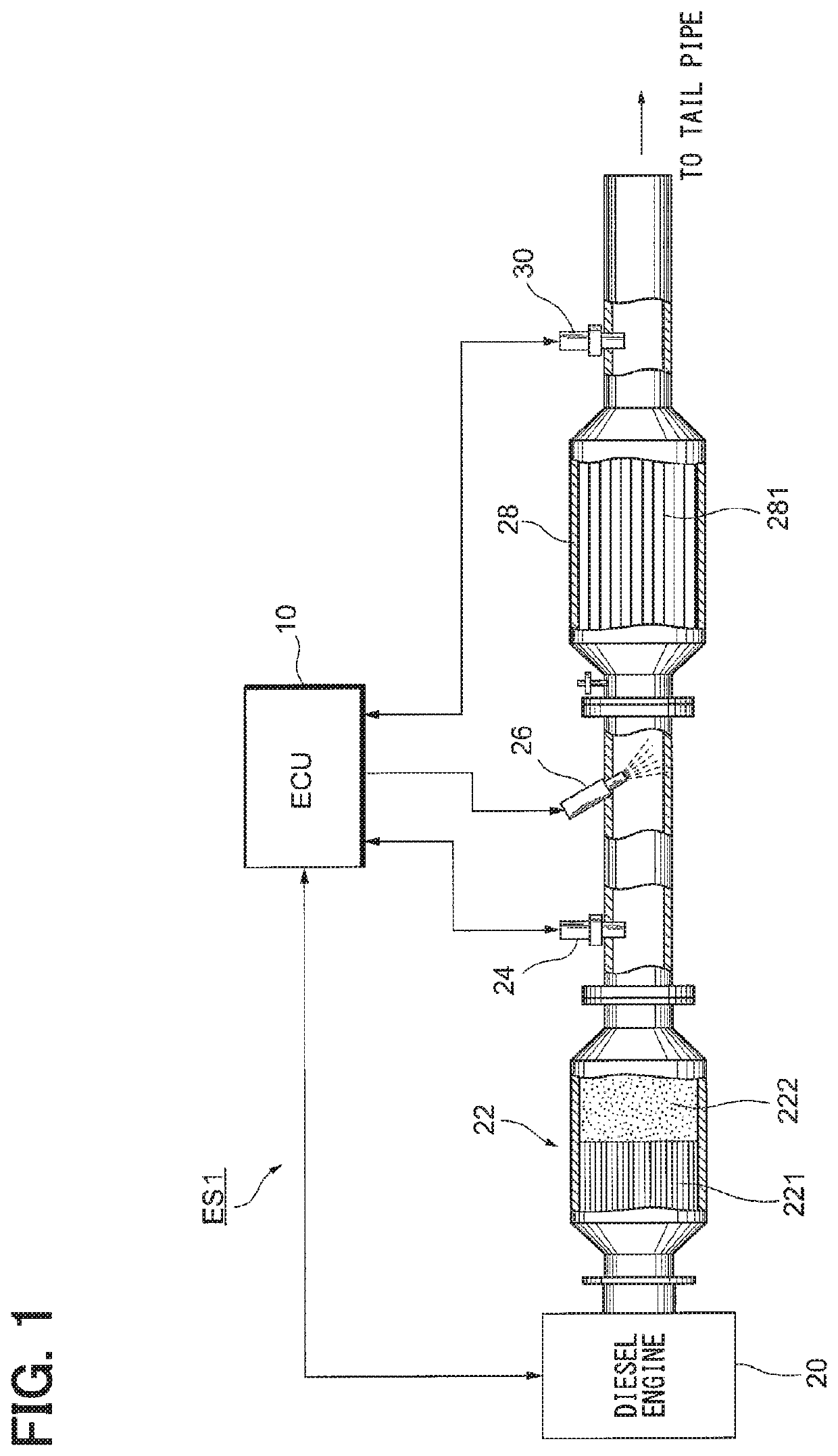
[0027]As illustrated in FIG. 1, an ECU 10 is a device that controls a diesel engine 20 and an engine exhaust system ES1 connected thereto. The ECU 10 functions to control a behavior of the diesel engine 20. The ECU 10 adjusts a fuel injection valve opening degree based on an accelerator opening degree and an engine rotation speed.

[0028]In the engine exhaust system ES1, a diesel oxidation catalyst converter 22 and a selective catalytic reduction (SCR) catalytic converter 28 are disposed in this order from the diesel engine 20 side. The diesel oxidation catalyst converter 22 has a diesel oxidation catalyst (DOC) 221 and a diesel particulate filter (DPF) 222.

[0029]The diesel oxidation catalyst converter 22, which removes a harmful substance from exhaust gas by oxidation or reduction, is a device that collects particulate matter (PM) which has carbon and the like in particular.

[0030]A ceramic carrier, an oxide mixture having aluminum oxide, cerium dioxide, and zirconium dioxide as its c...

second embodiment

[0095]An engine exhaust system ES2, in which the ECU 10 according to the first embodiment is divided into an ECU 10A and an SCU 40, will be described as a second embodiment with reference to FIGS. 9, 10, and 11.

[0096]As illustrated in FIG. 9, the engine control unit (ECU) 10A and the sensor control unit (SCU) 40 are disposed in the engine exhaust system ES2. The ECU 10A is a device that controls the diesel engine 20 and the engine exhaust system ES2 connected thereto. The ECU 10A functions to control a behavior of the diesel engine 20. The ECU 10A adjusts a fuel injection valve opening degree based on an accelerator opening degree and an engine rotation speed. The components other than the ECU 10A, the SCU 40, and a NOx sensor 24A are similar to those of the first embodiment, and thus description thereof will be omitted herein.

[0097]Currents outputted by the NOx sensor 24A and the NOx sensor 30 are detected by the SCU 40. The SCU 40 detects a gas amount, performs gas sensitivity det...

third embodiment

[0119]A NOx sensor in which a pump cell and a sensor cell are disposed in different chambers separated from each other can be used as well as a NOx sensor in which the pump cell 246 and the sensor cell 248 are disposed in a single chamber as in the case of the NOx sensor 24 according to the first embodiment and as in the case of the NOx sensor 24A according to the second embodiment.

[0120]FIG. 12 is a diagram illustrating schematic configurations of a gas sensor control device 100 and a NOx sensor 70 according to a third embodiment.

[0121]The gas sensor control device 100 and the NOx sensor 70 are mounted in a vehicle that is provided with an internal combustion engine. NOx concentration in exhaust gas of the engine is detected by the NOx sensor 70 being controlled by the gas sensor control device 100.

[0122]In the following description, a left side in FIG. 12 is a tip side of the NOx sensor 70 and a right side in FIG. 12 is a rear end side of the NOx sensor 70.

[0123]A first pump cell ...


PUM

PropertyMeasurementUnit
Currentsaaaaaaaaaa
concentrationaaaaaaaaaa
voltageaaaaaaaaaa

Abstract

A gas concentration detection device includes a pump cell, a sensor cell, a monitor cell, a sensor current detection unit detecting a current outputted by the sensor cell, a monitor current detection unit detecting a current outputted by the monitor cell, a voltage adjustment unit adjusting a pump cell voltage applied to the pump cell, and a sensitivity determination unit determining a gas sensitivity of at least one of the sensor cell or the monitor cell. The voltage adjustment unit changes the pump cell voltage from a target voltage into a detection voltage where the concentration of the residual oxygen supplied to the sensor cell and the monitor cell is increased. The sensitivity determination unit determines the gas sensitivity based on a detection current detected by at least one of the sensor current detection unit or the monitor current detection unit in accordance with the concentration of the residual oxygen.

Description

CROSS REFERENCE TO RELATED APPLICATION[0001]This application is the U.S. national phase of International Application No. PCT / JP2015 / 003716 filed on Jul. 24, 2015 which designated the U.S. and claims priority to Japanese Patent Application No. 2014-151790 filed on Jul. 25, 2014 and Japanese Patent Application No. 2015-138342 filed on Jul. 10, 2015, the entire contents of each of which are incorporated herein by reference.TECHNICAL FIELD[0002]The present disclosure relates to a gas concentration detection device that detects a specific gas component concentration in exhaust gas of an internal combustion engine.BACKGROUND ART[0003]A nitrogen oxide (NOx) sensor is known as a sensor that detects the concentration of NOx as one of the specific gas components contained in the exhaust gas discharged from an internal combustion engine. The NOx sensor is placed on, for example, the downstream side of a selective reduction-type NOx catalyst in a diesel engine exhaust gas purification system us...

Claims


Application Information

Patent Timeline
Patent Type & Authority Patents(United States)
IPC IPC(8): G01N27/406G01N27/41G01N27/407G01N27/409G01N27/416G01N27/26
CPCG01N27/4065G01N27/4073G01N27/41G01N27/407G01N27/416G01N27/409G01N27/26
Inventor KAYAMA, RYOZOYAMASHITA, YUKIHIRO
Owner DENSO CORP
Why Eureka
Try Eureka