
Sensor for wear measurement, method of making, and method of operating same

a technology of wear measurement and sensor, which is applied in the direction of sliding contact bearings, mechanical equipment, instruments, etc., can solve the problems of inability to fully wear out the bearing, etc., and achieve the effect of increasing the peel strength

Active Publication Date: 2014-04-17
NEW HAMPSHIRE BALL BEARINGS
View PDF4 Cites 11 Cited by
  • Summary
  • Abstract
  • Description
  • Claims
  • Application Information

AI Technical Summary

Benefits of technology

The patent describes a way to increase the strength of the adhesion between a wear sensor and its race or wear liner by creating small openings in the substrate and electrode. This allows an adhesive to flow through and improve the peel strength, making it more durable and reliable.

Problems solved by technology

The replacement of a bearing before it is fully worn out may be wasteful, but waiting too long to replace a bearing can be catastrophic in some applications, particularly with rotorcraft and aircraft.
Bearings with multiple optical fibers were disclosed to try to remedy this defect, but the overall complexity required for this measurement rendered the solution cost prohibitive.

Method used


Image

  • Sensor for wear measurement, method of making, and method of operating same
  • Sensor for wear measurement, method of making, and method of operating same
  • Sensor for wear measurement, method of making, and method of operating same

Examples


Embodiment Construction

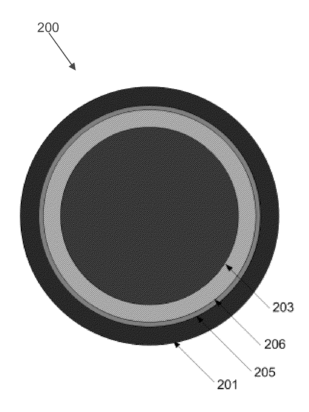
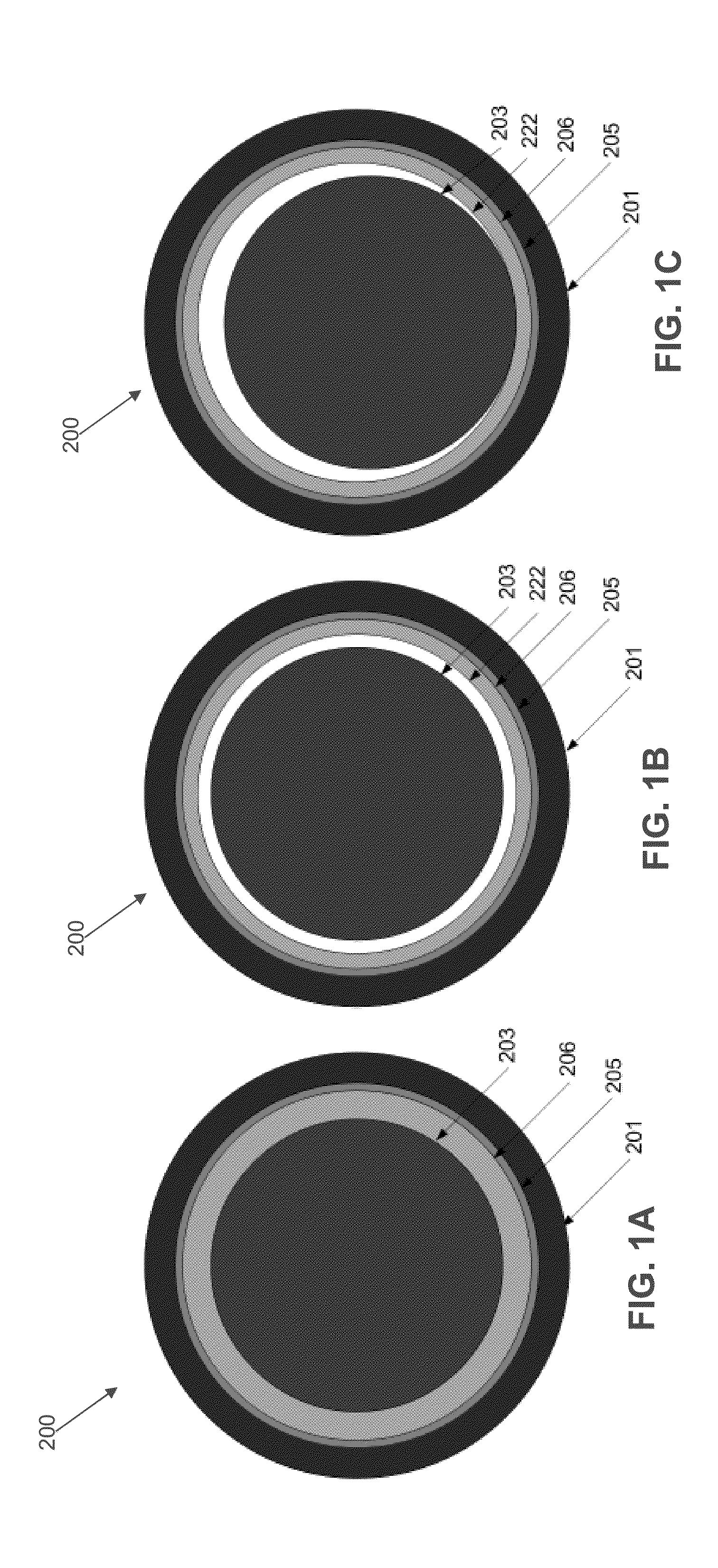
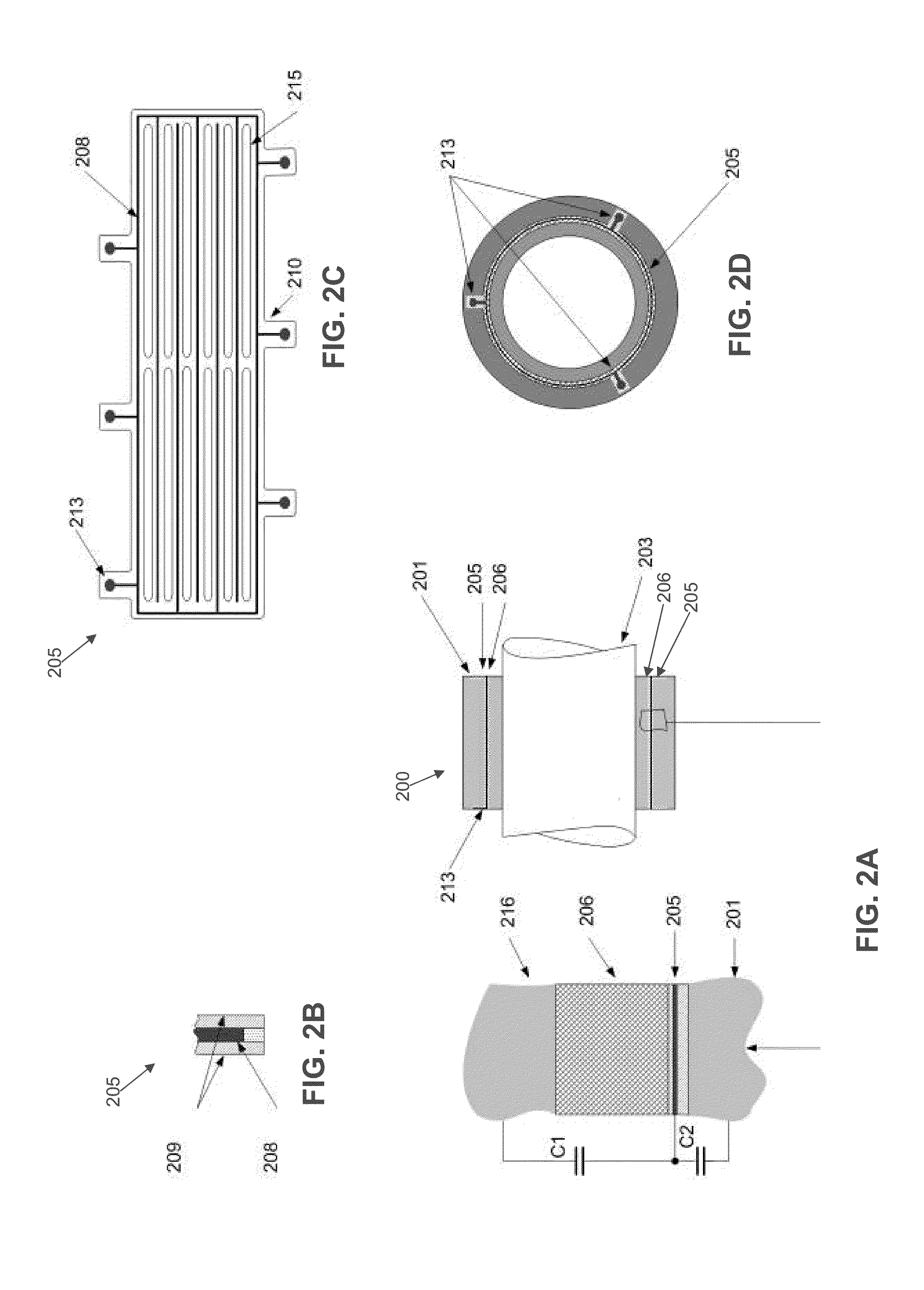
[0036]The present invention comprises an insulating wear liner with a sensor that is positioned either within the liner or placed on the non-wearing surface of the liner. The sensor is comprised of a conductive electrode and one or more pads for interrogating the electrical properties of the sensor. The liner is situated between the race and the moving part.

[0037]By way of example but not limitation, a sensor may be positioned inside of the wear liner of a sleeve bearing, and the capacitance between the wear liner and the shaft can be calculated in the new condition of the shaft and wear liner, and after wear by a shaft.

[0038]Looking now at FIG. 1A, FIG. 1 illustrates a new sleeve bearing with a sensor inserted into the wear liner according to this invention.

[0039]The new, unused sleeve bearing is assembled with a shaft which has radius Rshaft. The shaft is centered in the bearing, concentric with the race, which has a radius Rrace. The sensor conductive electrode is positioned insi...


PUM


Abstract

A wear sensor comprising:an insulating substrate having a top surface and a bottom surface;a conductive electrode formed on said top surface of said insulating substrate;an insulating wear lining material having a first side secured to said top surface of said insulating substrate and conductive electrode, an opposite second side that will be worn down by relative motion between the wear sensor and a moving component;one or more contact points where the electrical properties between the electrode and the moving component can be measured; andone or more perforations through the thickness of the substrate and electrode, through which an adhesive may flow, thereby increasing the peel strength between the wear sensor and race or between the wear sensor and the wear liner.

Description

REFERENCE TO PENDING PRIOR PATENT APPLICATION[0001]This patent application claims benefit of pending prior U.S. Provisional Patent Application Ser. No. 61 / 713,735, filed Oct. 15, 2012 by Iosif Izrailit et al. for SENSOR FOR WEAR MEASUREMENT, METHOD OF MAKING, AND METHOD OF OPERATING SAME (Attorney's Docket No. NANO-19 PROV), which patent application is hereby incorporated herein by reference.FIELD OF THE INVENTION[0002]This invention relates to wear sensing devices in general, and more particularly to a sensor suited to the measurement of wear in bearings that employ a low friction wear lining material, instead of balls or rollers to support the load. More particularly, the invention relates to the electrical measurement of capacitance or other electrical impedance parameters between a movable surface and an electrode, which may be positioned within or on the back side of the wear liner, and its correlation to wear.BACKGROUND OF THE INVENTION[0003]Condition based maintenance program...

Claims


Application Information

Patent Timeline
IPC IPC(8): G01N27/22G01N27/02
CPCG01N27/02G01N27/221G01N3/56F16C17/02F16C17/246F16C23/043G01N27/22
Inventor IZRAILIT, IOSIFCARNAHAN, DAVID L.DREW, GRANT A.SOELCH, RICHARD R.
Owner NEW HAMPSHIRE BALL BEARINGS
Learn More