Apparatus for ultra high vacuum thermal expansion compensation and method of constructing same

a technology of thermal expansion compensation and apparatus, applied in the manufacture of x-ray tubes, electrode systems, electric discharge tubes/lamps, etc., can solve the problems of shortened life, catastrophic failure of known bearing designs, and g-loading on x-ray tubes and particularly on targets

Active Publication Date: 2014-04-17
GENERAL ELECTRIC CO
View PDF3 Cites 2 Cited by
  • Summary
  • Abstract
  • Description
  • Claims
  • Application Information

AI Technical Summary

Problems solved by technology

Generally the mechanical loading on an x-ray tube increases as the square of the gantry rotational speed, thus increased gantry speeds have lead to enormous g-loading on the x-ray tube and particularly on the target.
As such, known bearing designs may fail either catastrophically or through a shortened life due to wear in these increased g-load conditions.
Increased gantry speeds can also cause relatively large mechanical deflections of the target support structure (shaft, bearing & target) that can cause focal spot motion or other sources of image quality problems.
The differences of material CTEs and the overall length of the relatively large parts can cause large differential thermal growth between the shaft and its linked components.
The weld or braze joints therefore can present modes of failure that may include a vacuum leak at the joint or a mechanical joint failure that can even lead to a catastrophic tube failure.
However, although component parts can be designed that minimize the stresses that result at temperature, not all thermal conditions are the same for the x-ray tube.
For instance, x-ray tubes operat

Method used


Image

  • Apparatus for ultra high vacuum thermal expansion compensation and method of constructing same
  • Apparatus for ultra high vacuum thermal expansion compensation and method of constructing same
  • Apparatus for ultra high vacuum thermal expansion compensation and method of constructing same

Examples


Embodiment Construction

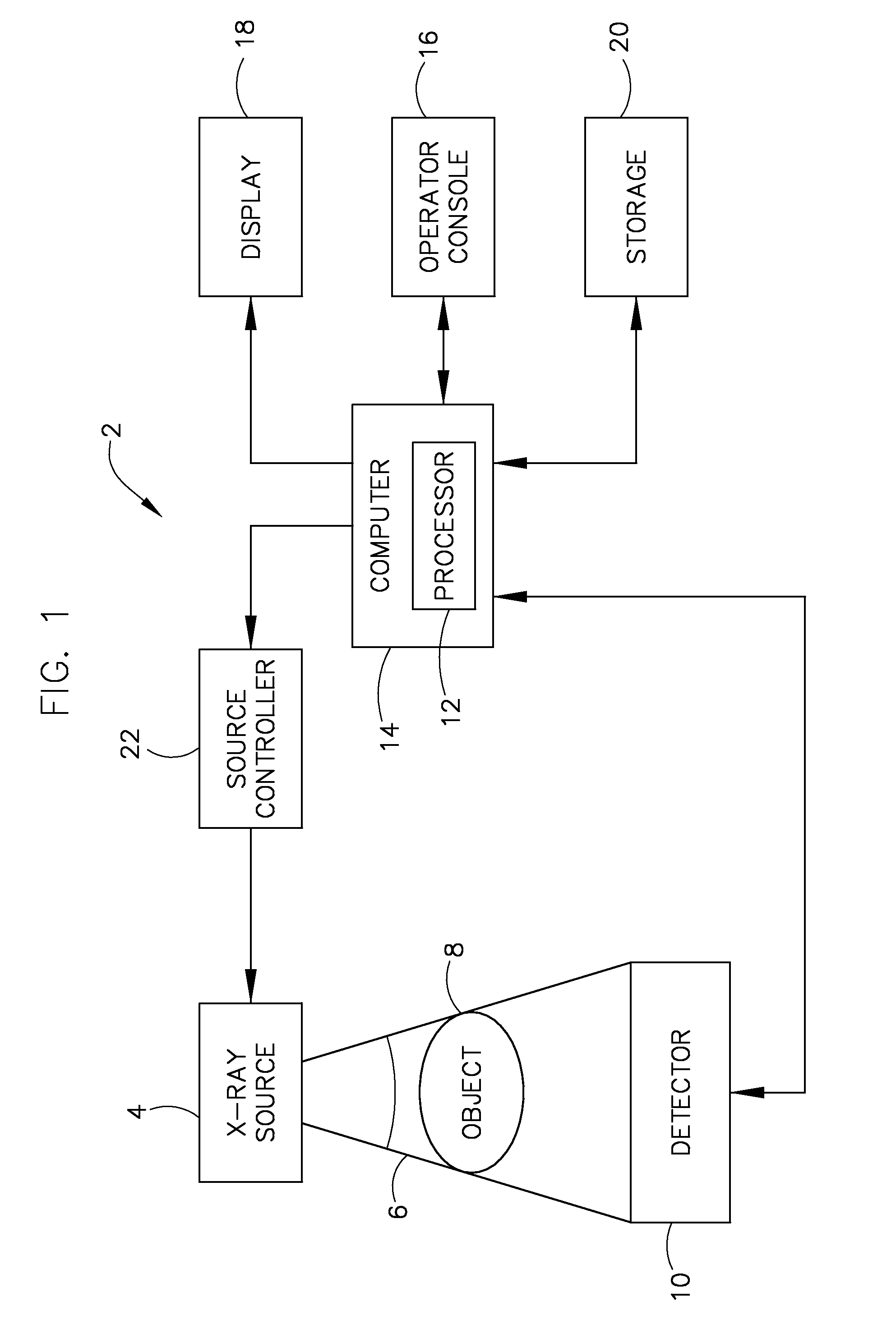
[0029]FIG. 1 is a block diagram of an embodiment of an x-ray imaging system 2 designed both to acquire original image data and to process the image data for display and / or analysis in accordance with the invention. It will be appreciated by those skilled in the art that the invention is applicable to numerous medical imaging systems implementing an x-ray tube, such as x-ray or mammography systems. Other imaging systems such as computed tomography (CT) systems and digital radiography (RAD) systems, which acquire image three dimensional data for a volume, also benefit from the invention. The following discussion of imaging system 2 is merely an example of one such implementation and is not intended to be limiting in terms of modality.

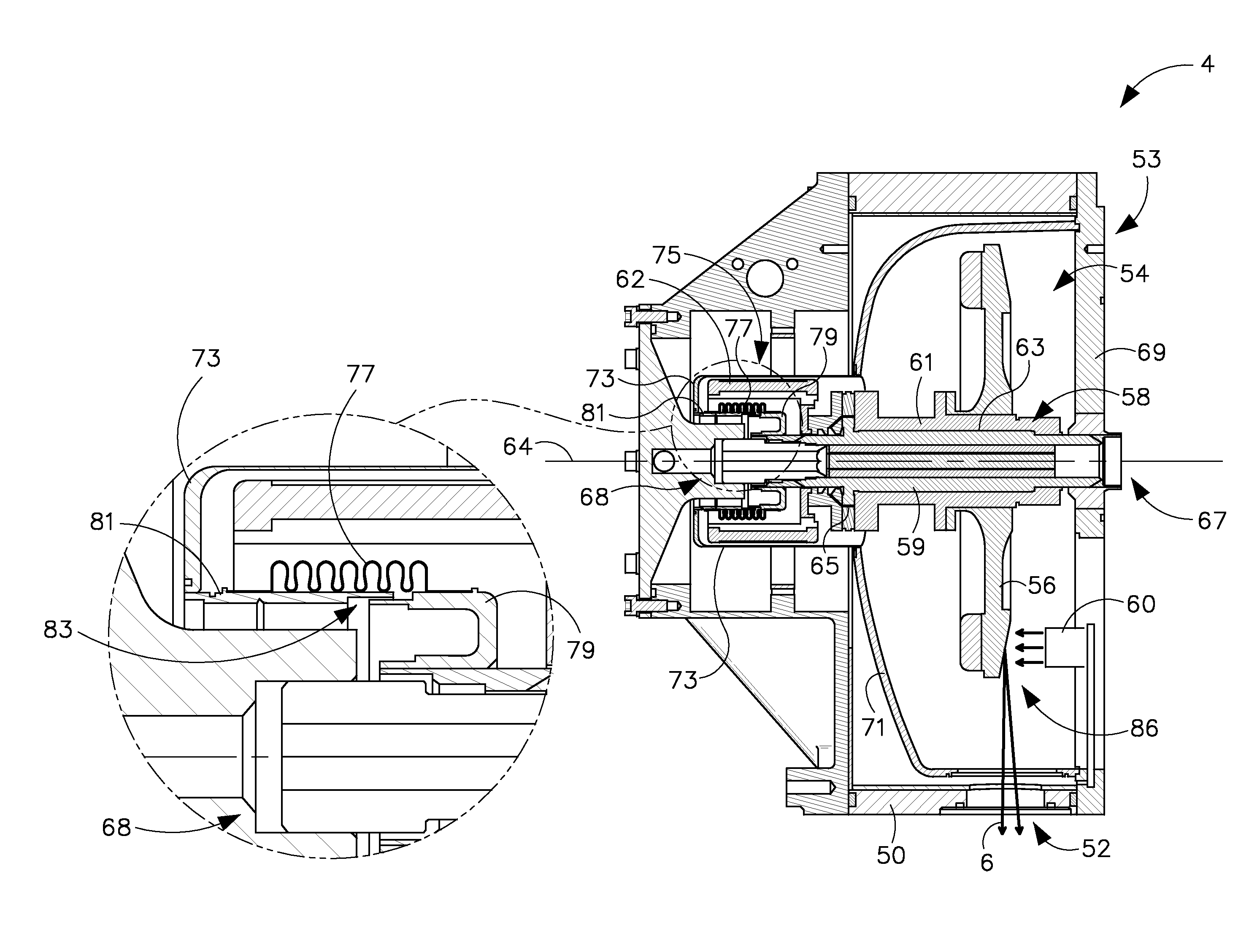
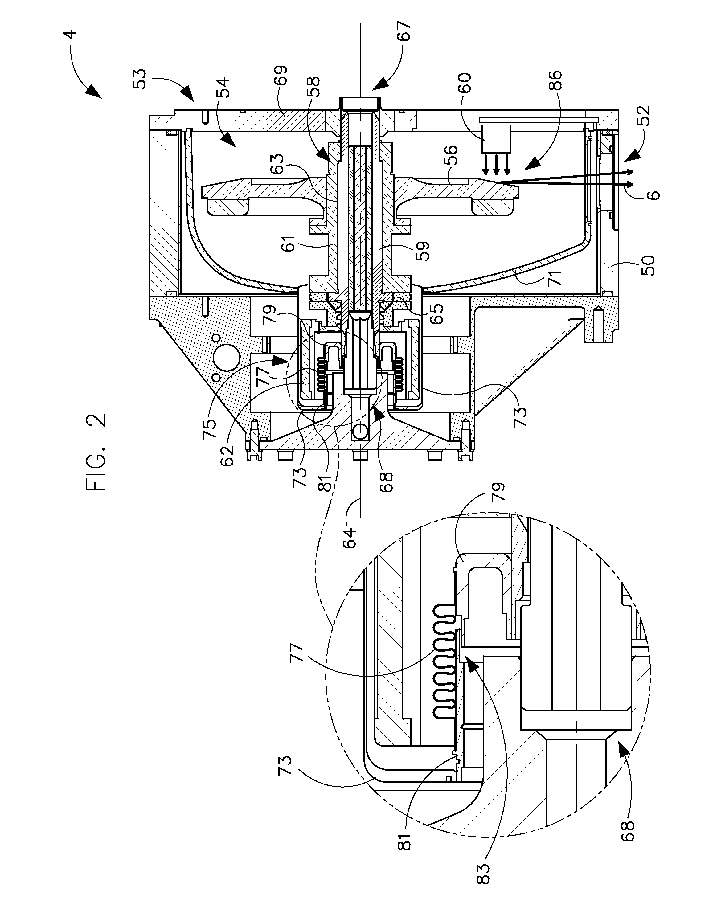
[0030]As shown in FIG. 1, imaging system 2 includes an x-ray tube or source 4 configured to project a beam of x-rays 6 through an object 8. Object 8 may include a human subject, pieces of baggage, or other objects desired to be scanned. X-ray source 4 may...


PUM


Abstract

An x-ray tube includes a frame forming a first portion of a vacuum enclosure, a rotating subsystem shaft positioned within the vacuum enclosure and having a first end and a second end, wherein the first end of the rotating subsystem shaft is attached to a first portion of the frame, a target positioned within the vacuum enclosure and attached to the rotating subsystem shaft between the first end and the second end, the target positioned to receive electrons from an electron source positioned within the vacuum enclosure, and a thermal compensator mechanically coupled to the second end of the rotating subsystem shaft and to a second portion of the frame, the thermal compensator forming a second portion of the vacuum enclosure.

Description

BACKGROUND OF THE INVENTION[0001]Embodiments of the invention relate generally to x-ray tubes and, more particularly, to an apparatus for forming an expansion joint and a method of constructing same.[0002]Computed tomography (CT) X-ray imaging systems typically include an x-ray tube, a detector, and a gantry assembly to support the x-ray tube and the detector. In operation, an imaging table, on which an object is positioned, is located between the x-ray tube and the detector. The x-ray tube typically emits radiation, such as x-rays, toward the object. The radiation typically passes through the object on the imaging table and impinges on the detector. As radiation passes through the object, internal structures of the object cause spatial variances in the radiation received at the detector. The detector converts the received radiation to electrical signals and then transmits data received, and the system translates the radiation variances into an image, which may be used to evaluate t...

Claims


Application Information

Patent Timeline
IPC IPC(8): H01J35/10H01J9/00
CPCH01J2235/1006H01J2235/1208H01J35/1017
Inventor LEGALL, EDWIN L.DAMM, RYAN MITCHELL
Owner GENERAL ELECTRIC CO
Why Eureka
Try Eureka