Method of controlling an optical output device for displaying a vehicle surround view and vehicle surround view system

a technology of optical output device and vehicle surround view, which is applied in the direction of special data processing applications, instruments, electric digital data processing, etc., can solve problems such as user disturbance, and achieve the effect of reducing storage space requirements and reducing the potential for dangerous distraction of users

Active Publication Date: 2014-04-17
HARMAN BECKER AUTOMOTIVE SYST
View PDF17 Cites 14 Cited by
  • Summary
  • Abstract
  • Description
  • Claims
  • Application Information

AI Technical Summary

Benefits of technology

[0021]In particular, there may be large numbers of possible combinations of virtual camera positions and possible display control information for the different vehicle components. It may be advantageous to calculate the graphical representation of the vehicle component based on the display control information and the virtual camera position each time, rather than provision a set of predefined graphical representations, for example, in the form of a image data, for each combination of camera position and display control information. Storage space requirements may be reduced when it is not required to store graphical representations for each combination of camera position and display control information. The display control information may be interpreted and the graphical output may be calculated and provided to overcome such deficiencies.
[0022]Moreover, displaying the vehicle surround view may comprise dynamic animation of the at least one vehicle component. For example, it may be possible to animate the turning of the wheels, the flashing of the turn indicators, or the opening and closing of the window pane. When such a dynamic animation of the vehicle model is provided, the user may more intuitively perceive the vehicle surround view. A more realistic vehicle surround view is provided. This is because the dynamically animated vehicle model fits into the dynamic surrounding provided by the vehicle surround view itself. A contrast between the moving background and the static vehicle model is avoided and therefore the potential for dangerous distraction of the user is reduced further.
[0023]In particular, it is possible that the at least one vehicle component is selected from a group comprising: wheel, steering wheel, window pane, front lights, rear lights, sun roof, vehicle body lacquering, turn indicator, or vehicle occupants. The adaptation of the vehicle model for those vehicle components has the effect that the vehicle model relates to the vehicle model as perceived by the user in real life. For example, the turning angle of the wheels may be adapted according to the current driving situation of the vehicle. When the vehicle is moving, the background in the vehicle surround view will be moving with respect to the vehicle model. When the wheels are rotating according to the velocity of the vehicle, the vehicle model and the background obtained from image sensors provide an intuitively perceivable impression on the user.

Problems solved by technology

However, it has been observed that a combination of the dynamic displaying of the vehicle surrounding with a static vehicle model causes disturbance to the user.
The perception of a static and predefined vehicle model with no indications of movement in combination with a moving background is known to cause distraction.

Method used


Image

  • Method of controlling an optical output device for displaying a vehicle surround view and vehicle surround view system
  • Method of controlling an optical output device for displaying a vehicle surround view and vehicle surround view system
  • Method of controlling an optical output device for displaying a vehicle surround view and vehicle surround view system

Examples


Embodiment Construction

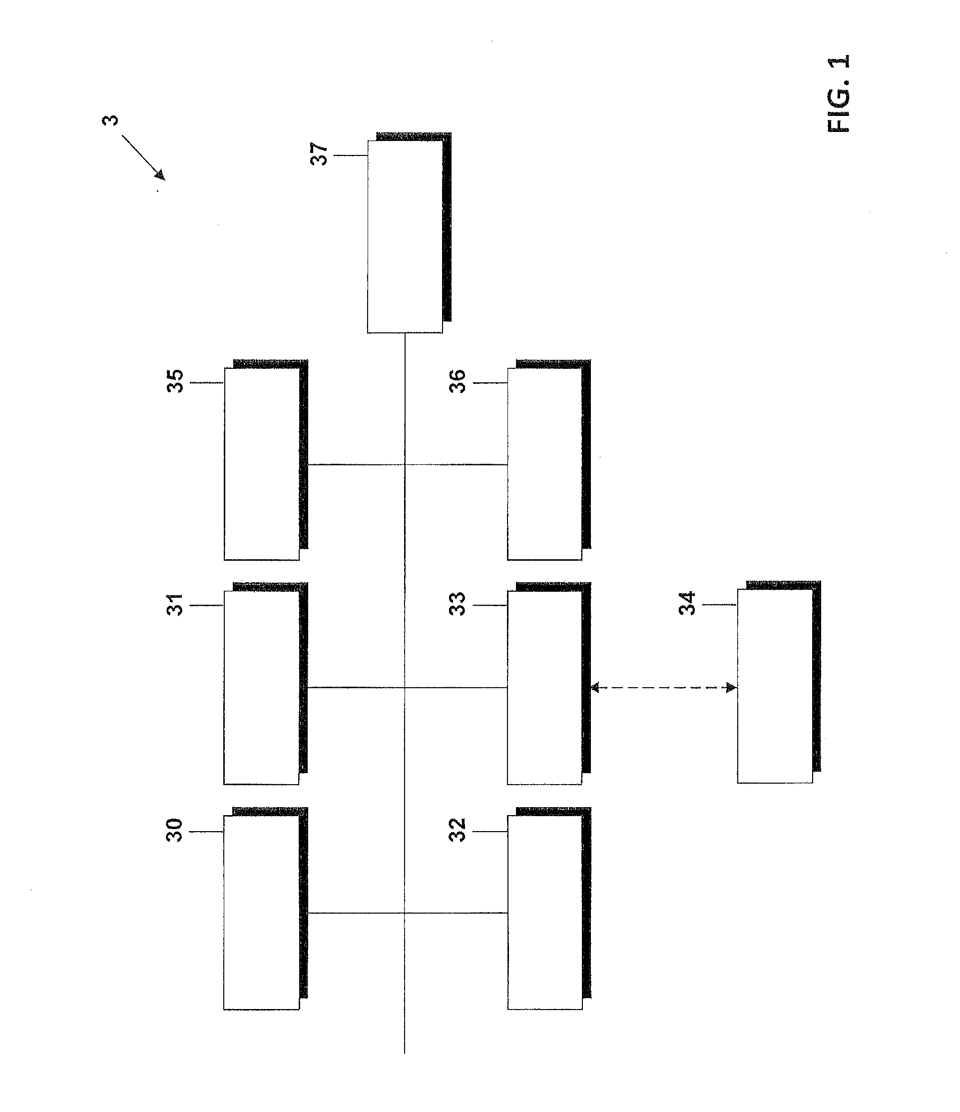
[0033]FIG. 1 is a block diagram illustration of a vehicle surround view system 3. The system 3 comprises a processor 30 that is configured to determine display control information for different vehicle components 32, 34. In particular, it is further configured to control an optical output device 31 in order to adapt a vehicle model contained in a vehicle surround view to depict the vehicle components 32, 34 based on the respective display control information.

[0034]For example, the optical output device 31 may be a display of a vehicle navigation system or a vehicle computer. Typically, modern navigation systems provide a display which can be used in certain situations to display the vehicle surround view rather than the information on navigation. Also, it is possible that the optical output device is a display only used by the vehicle surround view system itself.

[0035]The display control information is at least partly determined based on status information received from either the v...


PUM


Abstract

The present invention relates to controlling an optical output device for displaying a vehicle surround view containing a vehicle model, the method comprising determining display control information for at least one vehicle component, and controlling the optical output device to display the vehicle surround view such that the vehicle model is adapted to depict the at least one vehicle component according to the display control information.

Description

1. CLAIM OF PRIORITY[0001]This patent application claims priority from EP Application No. 11 185 124.2 filed Oct. 13, 2011, which is hereby incorporated by reference.2. FIELD OF TECHNOLOGY[0002]The invention relates to displaying a vehicle surround view and a vehicle surround view system.3. RELATED ART[0003]In recent years the use of image sensors in vehicles is proliferating. Often, these image sensors / cameras are used in a driver assist system in which the image sensors track the vehicle environment, identify objects, and warn the driver of possible dangerous driving situations. Furthermore, image sensors are used as rear view cameras which help the driver with parking the vehicle and which help the driver to be informed of any obstacle located behind the vehicle. The different image sensors provide a three-dimensional scene of the vehicle and its surroundings.[0004]However, it has been observed that a combination of the dynamic displaying of the vehicle surrounding with a static ...

Claims


Application Information

Patent Timeline
Patent Type & Authority Applications(United States)
IPC IPC(8): G06F17/00
CPCG06F17/00B60R1/00B60R2300/607B60R2300/80B60R2300/60
Inventor QUAST, JOHANNESSCHOLL, KAY-ULRICH
Owner HARMAN BECKER AUTOMOTIVE SYST
Why Eureka
Try Eureka