Gas turbine engine variable bleed valve for ice extraction

a gas turbine engine and variable technology, applied in the direction of engines, machines/engines, mechanical equipment, etc., can solve the problems of large particles not being drawn into the bleed duct, difficult to hold larger particles in the bleed flow, aircraft, marine and ground-based gas turbine engines,

Active Publication Date: 2014-04-24
GENERAL ELECTRIC CO
View PDF3 Cites 56 Cited by
  • Summary
  • Abstract
  • Description
  • Claims
  • Application Information

AI Technical Summary

Problems solved by technology

Because the bleed flow abruptly curves away from the direction of the compressor flow, it is very difficult to hold larger particles in the bleed flow because of their momentum.
This problem is common to aircraft, marine, and ground based gas turbine engines.
The problem associated with conventional bleed valve ducts and valve doors is that larger particles and amounts of particles such as ice are often not drawn into the bleed duct.
These two fundamental phenomena combine to cause substantial increase of water-to-air ratio in the combustor resulting in such aircraft engines being more susceptible to engine flame out problem in rain or hail storms.
The higher bypass ratio engines, having the large frontal area, also result in increased ice accretion on the booster inlet and booster stages during idle operation within an icing environment.
This results in increased ice shed during the acceleration, including sheds at or near maximum power operation.
It also increases the risk of compressor stall due to the ice sheds and more particularly to high speed rotor ice sheds, which historically has been an issue on two-shaft large engines, and will continue to be an issue on future large engines.
This increases the difficulty of bleeding sufficient amounts of air from downstream of the booster to the fan bypass duct for protecting boosters from stall.

Method used


Image

  • Gas turbine engine variable bleed valve for ice extraction
  • Gas turbine engine variable bleed valve for ice extraction
  • Gas turbine engine variable bleed valve for ice extraction

Examples


Embodiment Construction

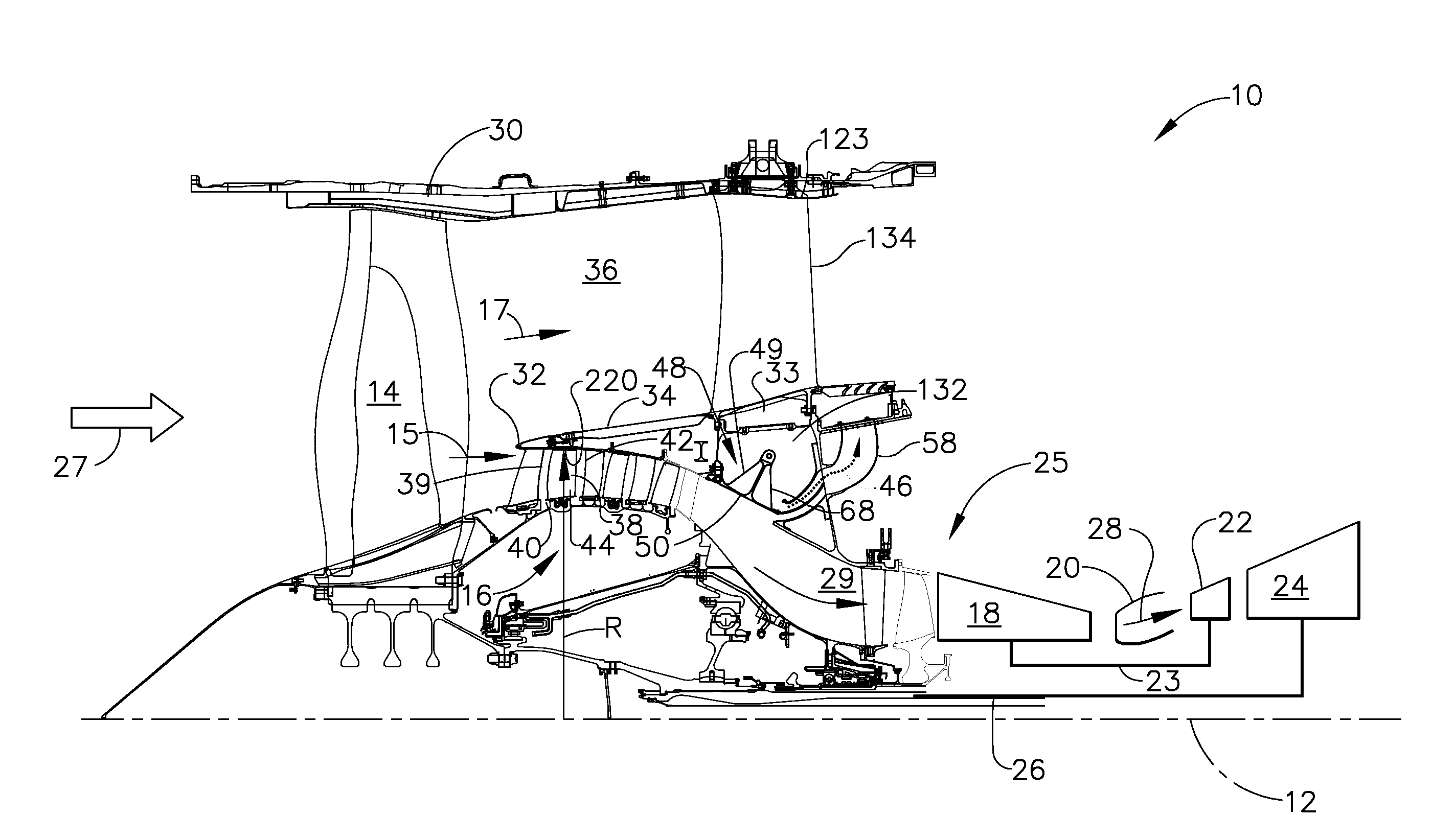
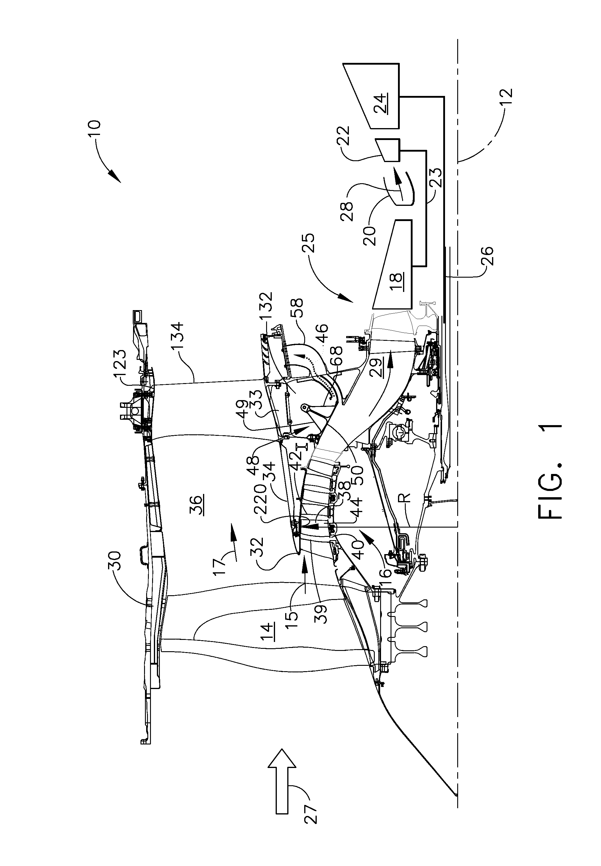
[0032]Illustrated in FIG. 1 is an exemplary aircraft turbofan gas turbine engine 10 circumscribed about an engine centerline 12 and suitably designed to be mounted to a wing or fuselage of an aircraft. The engine 10 includes, in downstream serial flow communication, a fan 14, a booster 16, a high pressure compressor 18, a combustor 20, a high pressure turbine (HPT) 22, and a low pressure turbine (LPT) 24. A core engine 25 includes the HPT or high pressure turbine 22 joined by a high pressure drive shaft 23 to the high pressure compressor 18 and the combustor 20. The LPT or low pressure turbine 24 is joined by a low pressure drive shaft 26 to both the fan 14 and the booster 16.

[0033]There are high bypass aircraft gas turbine engines such as some built by Rolls Royce that have more than two compressors and turbines. Rolls Royce, for example, has a three spool engine with three compressors each of which is driven by a different turbine. Thus, the VBV valve and door disclosed herein may...


PUM


Abstract

A variable bleed valve includes a variable bleed valve door disposed in a bleed inlet in transition duct and rotatable about an axis at or near a forward end of door. Valve is operable to open and close a bleed slot open to a booster bleed flowpath located outwardly of transition duct and having an airflow restrictor. Airflow restrictor may be variable such as a flapper valve. Booster bleed flowpath may pass through a bifurcated bleed duct including an inner passage radially bound by spaced apart inner and middle bleed walls and an outer passage radially bound by middle bleed wall and an outer bleed wall. Airflow restrictor may include an outlet area smaller than an inlet area of inner passage. Door seals against middle bleed wall to open inner passage and against outer bleed wall to open both passages.

Description

BACKGROUND OF THE INVENTION[0001]1. Field of the Invention[0002]The invention relates to gas turbine engine variable bleed valves and, more particularly, to such valves used to prevent surge and remove ice from duct between booster and core engine compressor.[0003]2. Description of Related Art[0004]It is well known in the gas turbine engine field to provide variable bleed valves (VBVs), typically, doors that open to provide a bleed flowpath to bleed off compressed air between the booster and core engine compressor of gas turbine engines. The air is often bled from what is referred to as a gooseneck flowpath between the booster and core engine compressor. Aircraft fan jet gas turbine engines and marine and industrial derivatives of such engines have employed various forms of curved flowpaths and VBV bleed doors that are retracted into the flowpath casing so as to form an entrance to a bleed duct that bleeds booster or low pressure compressor discharge airflow to draw particles out of...

Claims


Application Information

Patent Timeline
Patent Type & Authority Applications(United States)
IPC IPC(8): F02C7/00F02C9/18
CPCF02C7/052F02C9/18F02K3/075F04D27/0215F04D27/023F02C6/08F02C7/28F02C9/28F05D2260/606F05D2260/607
Inventor PRITCHARD, JR., BYRON ANDREWCALIFF, CHARLES DANIELWOOD, PETER JOHNHOLM, RAYMOND GUSTVAN DE WALL, ALLAN GEORGEPEZZI, PETER ALFRED
Owner GENERAL ELECTRIC CO
Why Eureka
Try Eureka