
Power supply filter and electronic circuitry including the same

a technology of power supply filter and electronic circuit, which is applied in the direction of power conversion systems, instruments, electrical apparatus, etc., can solve the problems difficult to reduce high-frequency noise to the desired level for an apparatus greatly affected by noise, and increasing the power loss of gate drives. , the effect of reducing power supply efficiency

Inactive Publication Date: 2014-04-24
PANASONIC INTELLECTUAL PROPERTY MANAGEMENT CO LTD
View PDF5 Cites 13 Cited by
  • Summary
  • Abstract
  • Description
  • Claims
  • Application Information

AI Technical Summary

Benefits of technology

The patent text presents a power supply filter that can efficiently reduce high-frequency noise. The filter includes a resistive element that absorbs high-frequency noise, which prevents spurious radiation caused by a current loop. The use of the resistive element results in a decreased power loss and increased power supply efficiency. Overall, the power supply filter described in the patent text can be used in various electronic circuits to reduce high-frequency noise and improve power efficiency.

Problems solved by technology

In a switching type DC-DC converter, mainly due to the effect of a parasitic inductor, high-frequency ringing noise, which occurs when power MOSFETs at a high supply voltage side (hereinafter, referred to as “high side”) and a low supply voltage side (hereinafter, referred to as “low side”) are turned OFF, occurs in a frequency band of 100 MHz to several hundreds MHz, and spurious radiation becomes a problem.
However, in the former method, due to heat generation of the power MOSFETs and increase in power loss of the gate drive, the power supply efficiency is decreased.
In the latter method, high-frequency noise is absorbed to some extent by the small-capacity capacitor, but it is difficult to reduce high-frequency noise to a desired level for an apparatus affected greatly by noise.
However, if the driving frequency is increased, an adverse effect occurs that high-frequency noise is increased and a stable operation of an apparatus becomes difficult.
In recent years, increase in the number of processes for countermeasures against EMI is a problem, and there is an urgent need to take measures against the problem.

Method used


Image

  • Power supply filter and electronic circuitry including the same
  • Power supply filter and electronic circuitry including the same
  • Power supply filter and electronic circuitry including the same

Examples


Embodiment Construction

[0020]Hereinafter, the present disclosure will be described in detail with reference to the drawings.

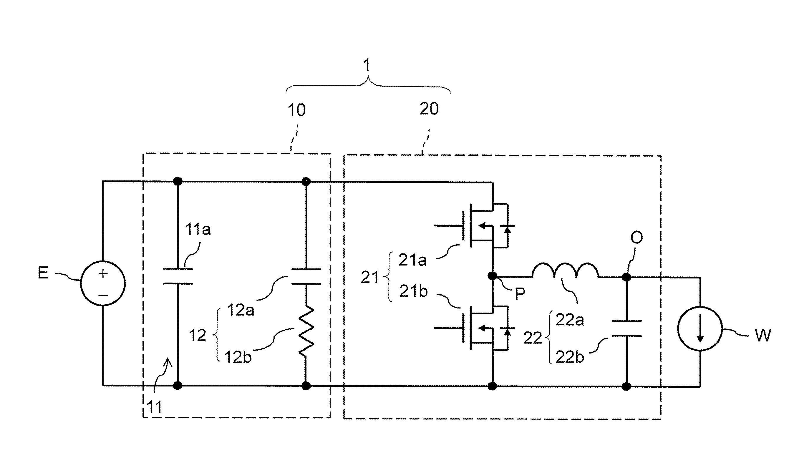
[0021]In the present disclosure, according to a second aspect based on the above-described aspect (first aspect), the power supply filter can be configured in which a resistance value of the resistive element is not lower than 0.1Ω.

[0022]In addition, in the present disclosure, according to a third aspect based on the second aspect, the power supply filter can be configured in which the resistance value of the resistive element is not lower than 0.5Ω and not higher than 1Ω.

[0023]In addition, in the present disclosure, according to a fourth aspect based on any one of the first to third aspects, the power supply filter can be configured in which the first filter circuit is composed of a first capacitor, the second filter circuit is composed of a second capacitor and the resistive element which are connected in series, and a capacitance value of the first capacitor is higher than a capac...


PUM


Abstract

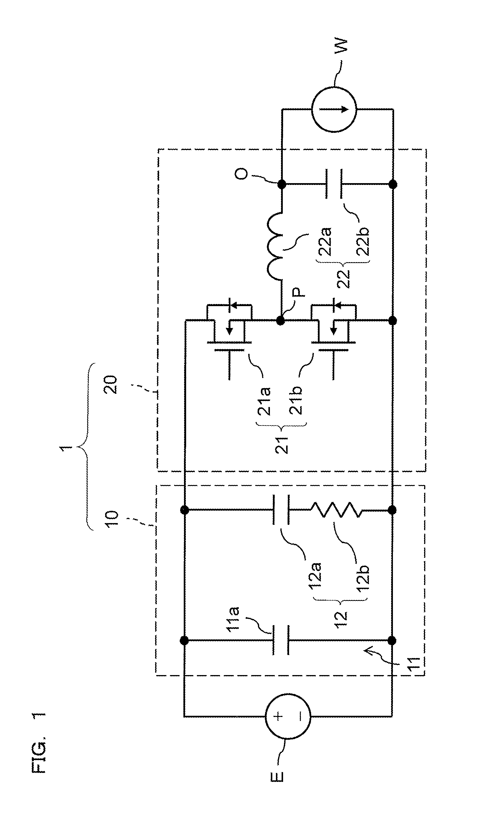
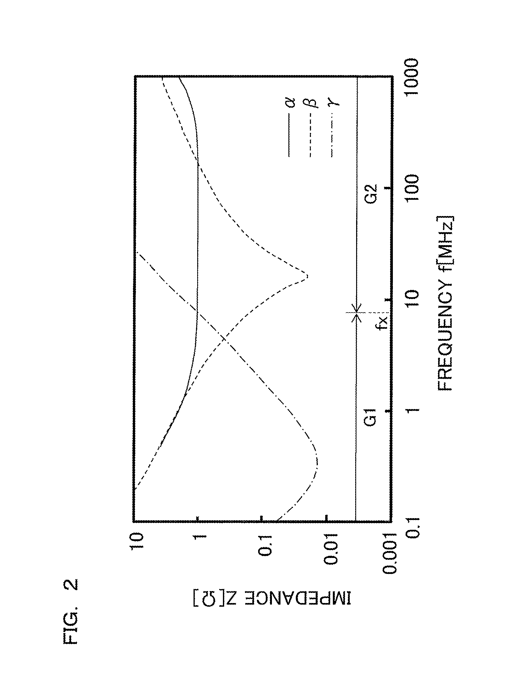
A power supply filter includes a first filter circuit and a second filter circuit connected in parallel with each other across supply voltage input terminals. The first filter circuit has such a low-pass characteristic that a gain of the first filter circuit is higher than that of the second filter circuit in a first band which is a low band. The second filter circuit includes a serially-inserted resistive element and has such a high-pass characteristic that the gain of the second filter circuit is higher than that of the first filter circuit in a second band which is a high band.

Description

BACKGROUND[0001]1. Field[0002]The present disclosure relates to a power supply filter.[0003]2. Description of the Related Art[0004]In a switching type DC-DC converter, mainly due to the effect of a parasitic inductor, high-frequency ringing noise, which occurs when power MOSFETs at a high supply voltage side (hereinafter, referred to as “high side”) and a low supply voltage side (hereinafter, referred to as “low side”) are turned OFF, occurs in a frequency band of 100 MHz to several hundreds MHz, and spurious radiation becomes a problem.[0005]In general, as a method for reducing high-frequency noise, a countermeasure method is used in which by inserting a series resistance into a gate drive circuit of a DC-DC converter, rising is made gradual and ringing is reduced.[0006]Meanwhile, in order to reduce the high-frequency noise, for example, a method of connecting a large-capacity bulk capacitor and a small-capacity capacitor for a countermeasure against noise in parallel at an input s...

Claims


Application Information

Patent Timeline
IPC IPC(8): H02M1/14H03H7/01
CPCH03H7/0138H02M1/14H02M1/126
Inventor NISHIMURA, TOSHIRO
Owner PANASONIC INTELLECTUAL PROPERTY MANAGEMENT CO LTD
Learn More