Liquid crystal display panel

a liquid crystal display and display panel technology, applied in static indicating devices, instruments, non-linear optics, etc., can solve the problem of much room for improvement, and achieve the effect of wide viewing angl

Inactive Publication Date: 2014-04-24
AU OPTRONICS CORP
View PDF2 Cites 7 Cited by
  • Summary
  • Abstract
  • Description
  • Claims
  • Application Information

AI Technical Summary

Benefits of technology

[0014]The invention is directed to a design of a LCD panel fo

Problems solved by technology

Although the LCD as listed above may achieve a wide viewing angle effect, problems

Method used


Image

  • Liquid crystal display panel
  • Liquid crystal display panel
  • Liquid crystal display panel

Examples


Embodiment Construction

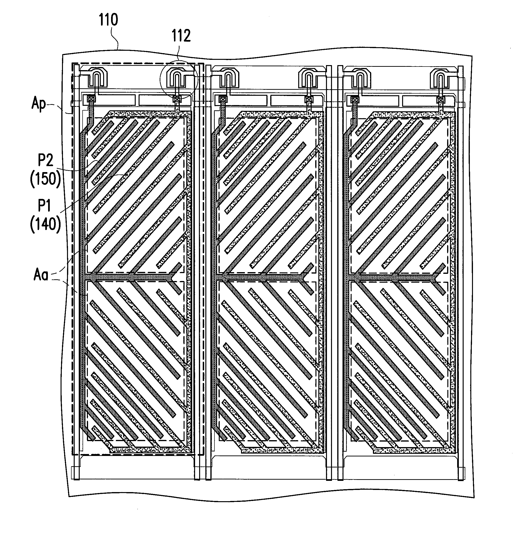
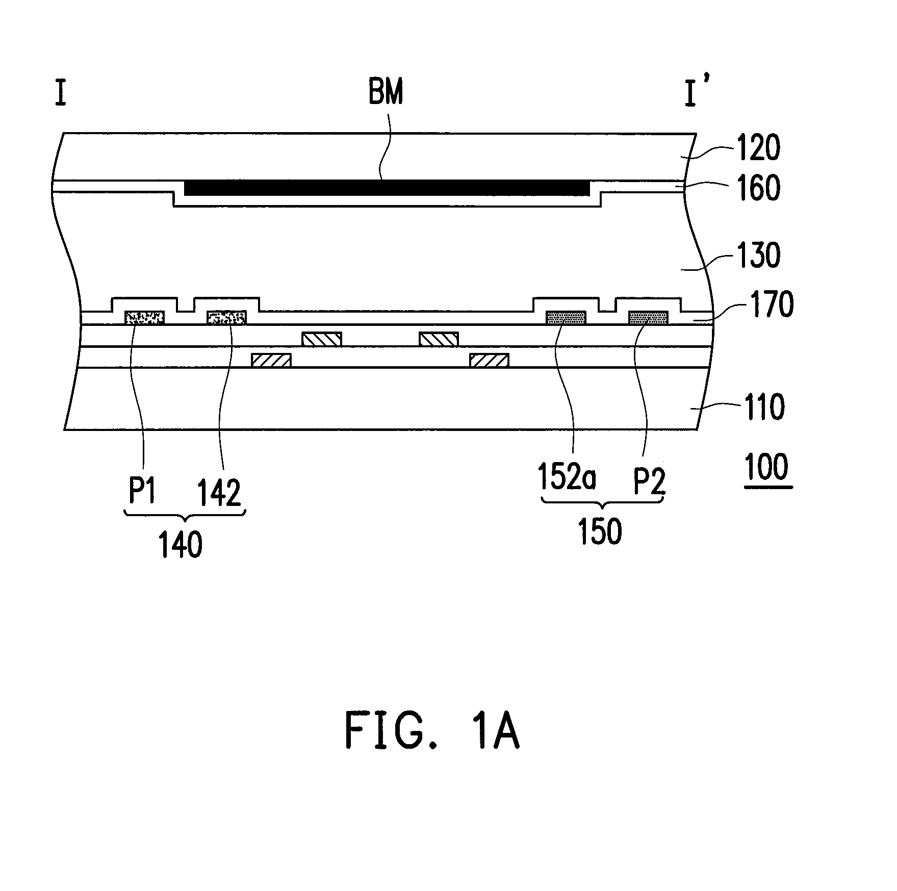
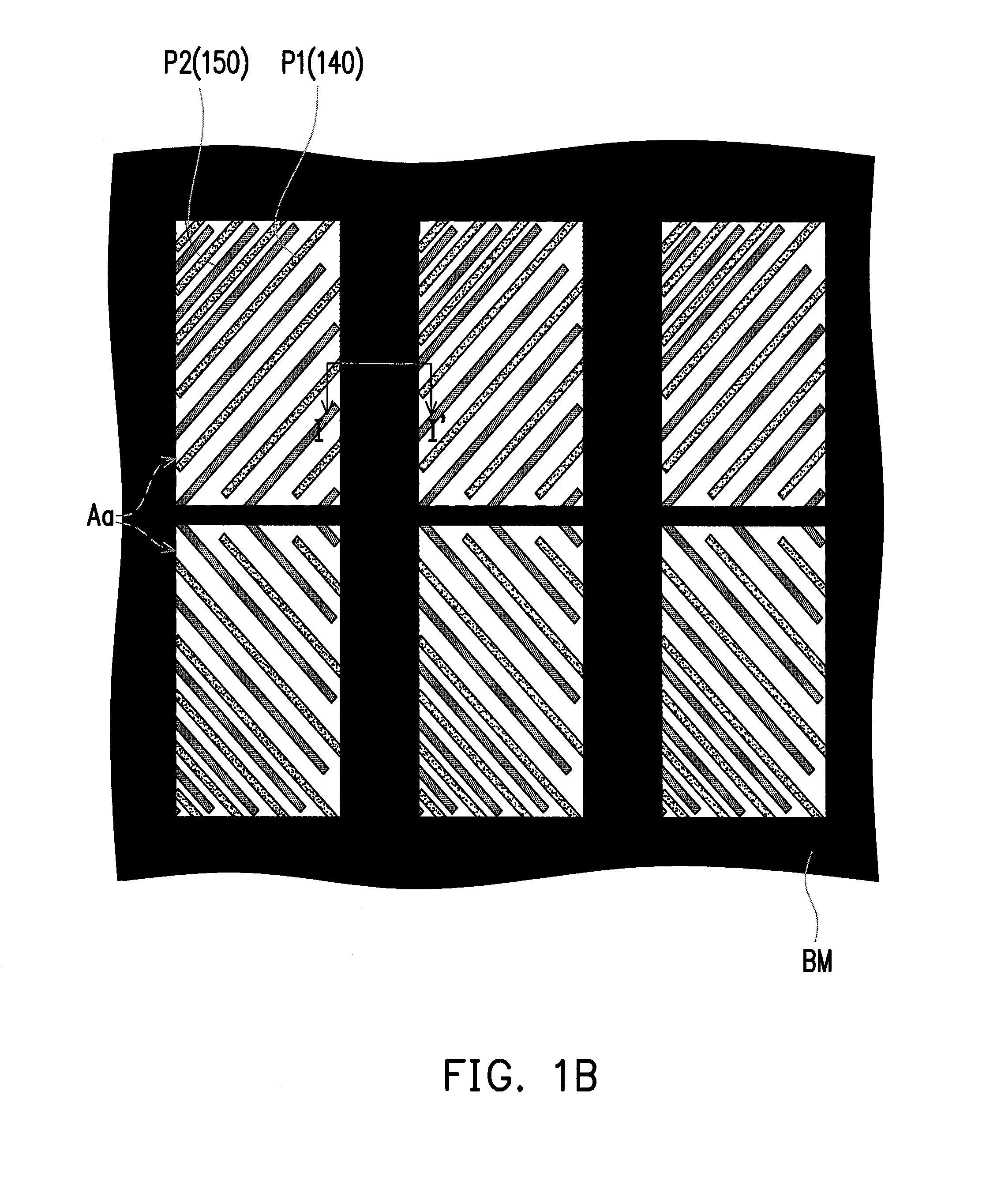
[0039]FIG. 1A is a schematic cross-sectional view of a liquid crystal display (LCD) panel according to an embodiment of the invention. FIG. 1B is a schematic top view of the LCD panel in FIG. 1A according to an embodiment of the invention, in which FIG. 1A is a schematic cross-sectional view illustrating an active device array substrate and layers thereon taken along the sectioning line I-I′ of FIG. 1B. Further, in order to simplify the description, certain layers in FIG. 1B are partially omitted.

[0040]Referring to FIG. 1A, a LCD panel 100 of the present embodiment includes an active device array substrate 110, an opposite substrate 120, a liquid crystal layer 130, a plurality of first pixel electrodes 140, a plurality of second pixel electrodes 150 and a light shielding layer BM.

[0041]The opposite substrate 120 is disposed opposite to the active device array substrate 110, and the liquid crystal layer 130 is located between the active device array substrate 110 and the opposite sub...


PUM


Abstract

A liquid crystal display panel having pixel regions includes a light shielding layer having opening regions corresponding to the pixel regions, first pixel electrodes and second pixel electrodes. Each first pixel electrode includes strip first pixel electrode patterns. Each second pixel electrode includes strip second pixel electrode patterns. Each opening region includes sub regions. Each of the strip first pixel electrode patterns and its neighboring strip second pixel electrode pattern in each of the sub regions are separated by an electrode spacing. Electrode spacings in different sub regions are different. An area of all the sub regions with the electrode spacings less than or equal to 12 micrometers accounts for less than or equal to 35% area of each opening region. An area of the other sub regions with the electrode spacings greater than 12 micrometers accounts for more than or equal to 65% area of each opening region.

Description

CROSS-REFERENCE TO RELATED APPLICATION[0001]This application claims the priority benefit of Taiwan application serial no. 101138953, filed on Oct. 22, 2012. The entirety of the above-mentioned patent application is hereby incorporated by reference herein and made a part of this specification.BACKGROUND OF THE INVENTION[0002]1. Field of the Invention[0003]The present invention generally relates to a display panel, and more particularly, to a liquid crystal display (LCD) panel.[0004]2. Description of Related Art[0005]Nowadays, the market demands the liquid crystal display (LCD) panel to develop its functions towards high contrast ratio, no gray scale inversion, little color shift, high luminance, full color, high color saturation, high response speed and wide viewing angle. Currently, the technologies capable of fulfilling the demands of wide viewing angle include the twist nematic (TN) LCD panel having a wide viewing film, the in-plane switching (IPS) LCD panel, the fringe field swit...

Claims


Application Information

Patent Timeline
IPC IPC(8): G02F1/1343G02F1/133
CPCG02F1/13306G02F1/134336G02F1/133512G02F1/134363G02F1/13624
Inventor TSAO, SAU-WENLU, MEI-JUCHEN, CHO-YANTING, TIEN-LUN
Owner AU OPTRONICS CORP
Why Eureka
Try Eureka