

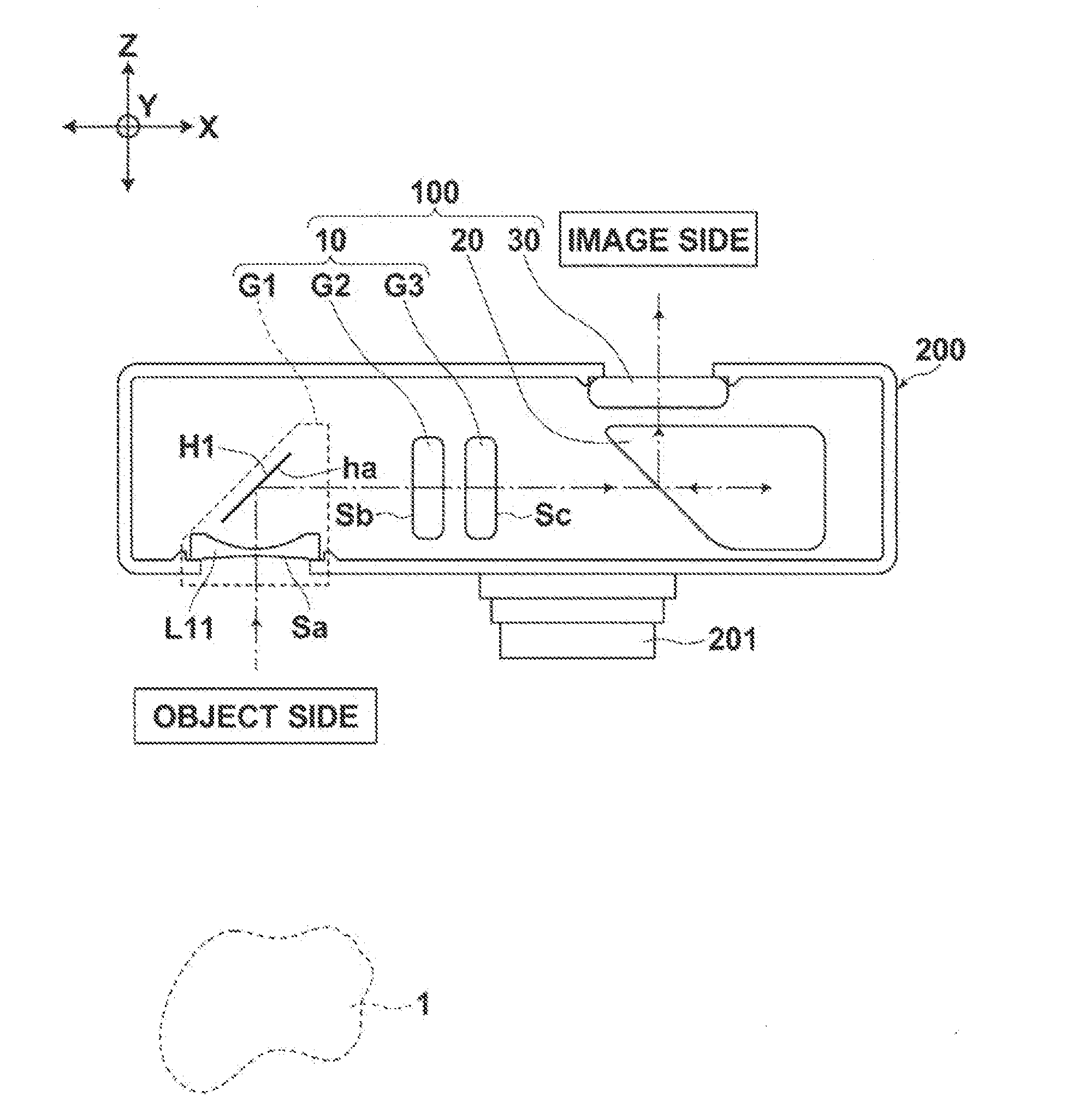
Real-image zoom viewfinder and imaging apparatus
a technology of which is applied in the field of real-image zoom viewfinder and imaging apparatus, can solve the problems of difficult to achieve sufficient thickness reduction, difficult to achieve the reduction of thickness while ensuring a zoom ratio of around 4:1, etc., and achieves the reduction of optical path length, shorter optical path length, and longer optical path length
- Summary
- Abstract
- Description
- Claims
- Application Information
AI Technical Summary
Benefits of technology
Problems solved by technology
Method used
Image

Examples
example 1
[0081]FIG. 6 is a diagram illustrating a developed view of the configuration and the optical path of the real-image zoom viewfinder of Example 1.
[0082]Table 1A, which will be described later, shows data about the real-image zoom viewfinder of Example 1. Lens data is shown in the upper table of Table 1A, and data relating to zoom of the real-image zoom viewfinder is shown in the lower table of Table 1A.
[0083]In the lens data shown in the upper table of Table 1A, each value in the column of “Surface number Si” represents the surface number of the i-th (i=1, 2, 3, . . . ) lens surface, or the like, where the number is sequentially increased from the most object-side surface toward the image side.
[0084]Each value in the column of “Radius of curvature Ri” represents the radius of curvature of the i-th (i=1, 2, 3, . . . ) surface. Each value in the column of “Surface interval Di” (i=1, 2, 3, . . . ) represents the surface interval between the i-th surface and the i+1-th surface along the ...
example 2
[0100]FIG. 7 is a diagram illustrating a developed view of the configuration and the optical path of the real-image zoom viewfinder of Example 2.
[0101]Table 2A shows data about the real-image zoom viewfinder of Example 2. Lens data is shown in the upper table of Table 2A, and data relating to zoom of the real-image zoom viewfinder is shown in the lower table of Table 2A.
TABLE 2AExample 2SurfaceRadiusSurfaceAbbenumber Siof curvature Riinterval DiRefractive index Njnumber νj*118.74221.8001.58364130.27*25.29651.4003∞7.6281.84666023.784∞D4532.1362.5001.49023357.45*6−13.8448D6721.34761.7501.48749070.23865.0217D89∞9.0001.49023357.4510∞0.50011∞19.125 1.49023357.4512∞3.3791345.6734.5001.49023357.45*14−10.3661Data relating to zoomSpecificationsWide-angle endTelephoto endFinder magnification: m0.431.72Angle of field: 2ω58.313.3Interval: D425.6482.458Interval: D611.0522.140Interval: D89.95442.056*aspherical surface
[0102]Table 2B shows aspherical coefficients representing the shape of each asph...
example 3
[0106]FIG. 8 is a diagram illustrating a developed view of the configuration and the optical path of the real-image zoom viewfinder of Example 3.
[0107]Table 3A shows data about the real-image zoom viewfinder of Example 3. Lens data is shown in the upper table of Table 3A, and data relating to zoom of the real-image zoom viewfinder is shown in the lower table of Table 3A.
TABLE 3AExample 3SurfaceRadiusSurfaceAbbenumber Siof curvature Riinterval DiRefractive index Njnumber νj*114.7921.8001.58364130.27*24.15671.4003∞7.6281.84666023.784∞D4519.43742.5001.49023357.45*6−12.4582D6714.27341.7501.48749070.23833.1381D89∞9.0001.49023357.4510∞0.50011∞19.125 1.49023357.4512∞2.0001323.00913.0001.49023357.45*14−12.9246Data relating to zoomSpecificationsWide-angle endTelephoto endFinder magnification: m0.301.21Angle of field: 2ω69.617.2Interval: D419.6871.454Interval: D60.5000.667Interval: D89.72027.786*aspherical surface
[0108]Table 3B shows aspherical coefficients representing the shape of each asph...
PUM
 Abstract
Description
Claims
Application Information