Objective lens, optical system and optical pickup apparatus

Inactive Publication Date: 2006-04-18
KONICA MINOLTA INC
View PDF2 Cites 8 Cited by
  • Summary
  • Abstract
  • Description
  • Claims
  • Application Information

AI Technical Summary

Benefits of technology

[0018]An optical element for an optical pickup device described in Item 1 is one equipped with a chromatic aberration correcting element and an objective lens that converges a light flux coming from the chromatic aberration correcting element, wherein the chromatic aberration correcting element is composed of plural ring-shaped zones divided by microscopic steps, and has, on at least one optical surface thereof, a ring-shaped zonal structure that is displaced in the direction of an optical axis on each boundary so that an optical path length for a light flux that has passed through an outer ring-shaped zone may be longer than that for a light flux that has passed through an inner ring-shaped zone, the objective lens is composed of plural ring-shaped zones divided by microscopic steps, and has, on at least one optical surface thereof, a ring-shaped zonal structure wherein adjoining ring-shaped zones generate a prescribed optical path difference f

Problems solved by technology

However, if chromatic aberration of the objective lens is not corrected, troubles such as recording failures caused by defocus

Method used


Image

  • Objective lens, optical system and optical pickup apparatus
  • Objective lens, optical system and optical pickup apparatus
  • Objective lens, optical system and optical pickup apparatus

Examples


Example

Example 1

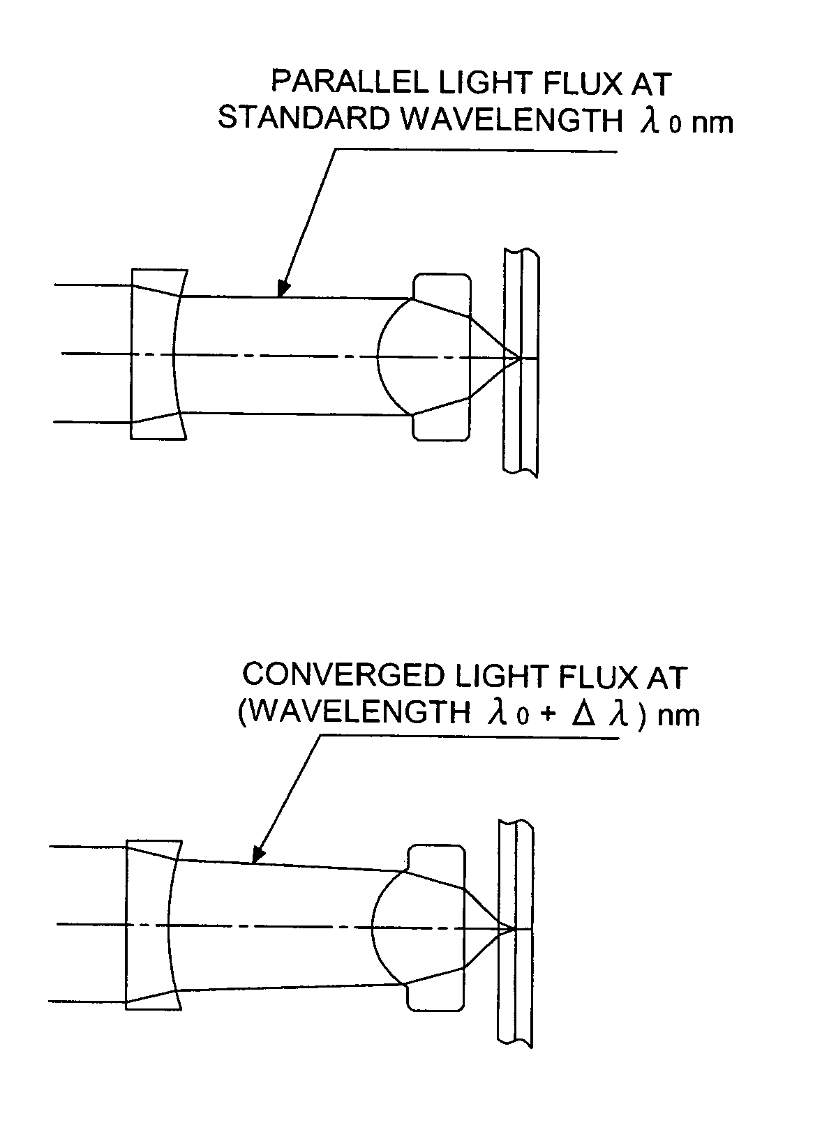
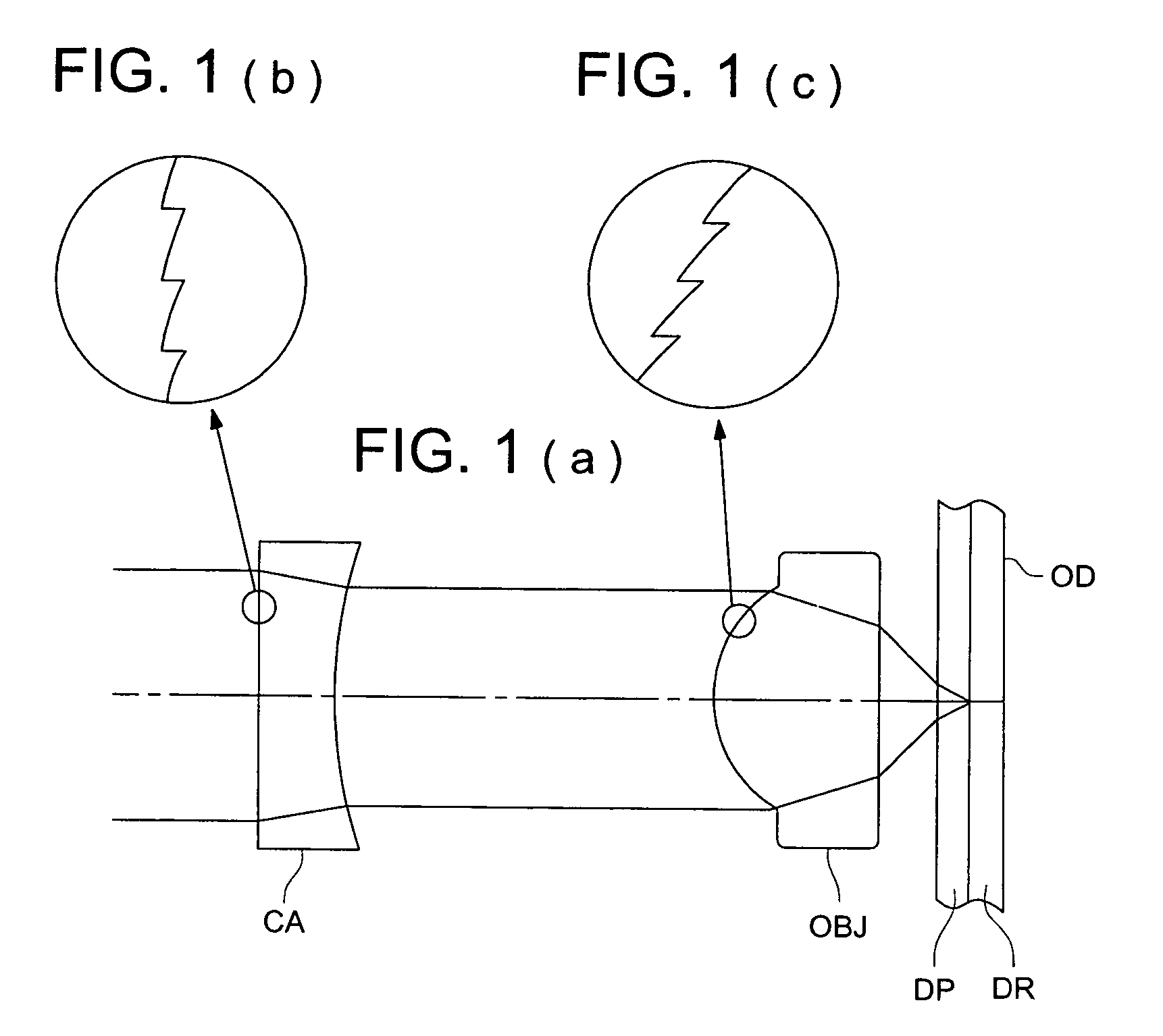
[0141]Lens data of the optical system for an optical pickup device in Example 1 are shown in Table 1. The present example is one preferable as optical system OS for an optical pickup device shown in FIG. 1, and it is composed of objective lens OBJ and of chromatic aberration correcting element CA arranged between parallel light fluxes between the objective lens OBJ and the light source. Both of the objective lens OBJ and the chromatic aberration correcting element CA represent a plastic lens. Incidentally, the chromatic aberration correcting element CA is designed so that it may have no aberration within a diameter of 3.4 mm on its surface where a light flux emerges (Second surface in Table 1).

[0142]TABLE 1SurfaceNo.r(mm)d(mm)NλνdRemarks0∞Light source1∞1.00001.5243256.5Chromatic aberration2  10.57935.0000correcting element3   0.94201.79001.5597356.3Objective lens4 −1.56000.39515∞0.08751.6184930.0Protective layer6∞

[0143]Coefficient of aspheric surfaceSecond surfaceThird surf...

Example

Example 2

[0155]Lens data of the optical system for an optical pickup device in Example 2 are shown in Table 2. The present example is one preferable as optical system OS for an optical pickup device shown in FIG. 1, and it is composed of objective lens OBJ and of chromatic aberration correcting element CA arranged between parallel light fluxes between the objective lens OBJ and the light source. Both of the objective lens OBJ and the chromatic aberration correcting element CA represent a plastic lens. Incidentally, the chromatic aberration correcting element CA is designed so that it may have no aberration within a diameter of 3.4 mm on its surface where a light flux emerges (Second surface in Table 2).

[0156]TABLE 2SurfaceNo.r(mm)d(mm)NλνdRemarks0∞Light source1∞1.00001.5243256.5Chromatic aberration2  10.57935.0000correcting element3   0.93911.78501.5597356.3Objective lens4 −1.58470.39505∞0.08751.6184930.0Protective layer6∞

[0157]Coefficient of aspheric surfaceSecond surfaceThird surf...

Example

Example 3

[0169]Lens data of the optical system for an optical pickup device in Example 3 are shown in Table 3. The present example is one preferable as optical system OS for an optical pickup device shown in FIG. 1, and it is composed of objective lens OBJ and of chromatic aberration correcting element CA arranged between parallel light fluxes between the objective lens OBJ and the light source. The objective lens OBJ is a glass lens having glass transition point of 285° C. (PG 325 made by SUMITA Optical Glass Co.), while, the chromatic aberration correcting element CA is a plastic lens. Incidentally, the chromatic aberration correcting element CA is designed so that it may have no aberration within a diameter of 3.4 mm on its surface where a light flux emerges (Second surface in Table 3).

[0170]TABLE 3SurfaceNo.r(mm)d(mm)NλνdRemarks0∞Light source1∞1.00001.5243256.5Chromatic aberration2  13.45425.0000correcting element3   0.90191.78001.5184370.5Objective lens4 −1.26660.40665∞0.08751....


PUM


Abstract

An optical system for use in an optical pickup apparatus has a chromatic aberration correcting element having plural ring-shaped zones divided with a stepped section in such a way that one of the neighboring ring-shaped zones located apart from the optical axis has a longer optical path than the other one located closer to the optical axis, and an objective lens having plural ring-shaped zones divided with a stepped section shaped in the optical axis direction in such a way that the stepped section causes a optical path difference between light fluxes having passed through the neighboring ring-shaped zones. The ring-shaped zonal structure of the chromatic aberration correcting element corrects a deviation of a focal point caused by the objective lens due to a wavelength fluctuation of an incident light flux coming into the optical system.

Description

BACKGROUND OF THE INVENTION[0001]The present invention relates to an optical system for an optical pickup device, an optical pickup device and an objective lens, and in particular, to an optical system for an optical pickup device, an optical pickup device and an objective lens which can achieve high density recording or reproducing for information.[0002]As is known as CD (compact disc) or DVD (digital versatile disc), an optical disc has been used for storage of digital data such as accumulation of music information and image information or storage of computer data. Further, with the recent advent of an information-oriented society, there are actual circumstances wherein large capacities of the optical discs are strongly demanded.[0003]In this case, an improvement of recording capacity (recording density) per a unit area can be realized by making a spot diameter of a light-converged spot obtained from the optical system for an optical pickup device, in the optical disc. Since this ...

Claims


Application Information

Patent Timeline
IPC IPC(8): G02B13/18G11B7/00G02B13/00G02B27/00G11B7/125G11B7/1353G11B7/1374G11B7/1378G11B7/1392
CPCG02B27/0037G02B27/4238G02B27/4272G11B7/13922G11B7/1374G11B7/1378G11B7/1353G02B13/00
Inventor KIMURA, TOHRUNOGUCHI, KAZUTAKA
Owner KONICA MINOLTA INC
Why Eureka
Try Eureka