Multipass Cell Using Spherical Mirrors While Achieving Dense Spot Patterns

a multi-spot pattern and optical path technology, applied in the field of optical multi-spot cell configuration, can solve the problems of interference etalon fringe pattern, cell limited spot number, and inability to easily transport instruments requiring such a long tube, so as to reduce the separation between adjacent spots, reduce fabrication costs, and reduce the effect of spherical mirrors

Active Publication Date: 2012-09-27
AERIS TECH INC
View PDF2 Cites 15 Cited by
  • Summary
  • Abstract
  • Description
  • Claims
  • Application Information

AI Technical Summary

Benefits of technology

[0016]While an important design goal is to achieve a dense spot pattern (i.e., minimizing the separation between adjacent spots), other criteria that may be considered when evaluating specific arrangements include one or more of the following: ensuring that the rays remain “within bounds” of the surface of the spherical mirror; creating a sufficiently long optical path length; location of the exit hole with respect to the entrance hole; and location of the exit hole with respect to the “last” spot's neighboring spots (ensuring that the physical process of forming a hole of sufficient size for the exit beam doesn't come too near another spot on the mirror).
[0017]It is an advantage of the arrangement of the present invention that simple plano-concave spherical glass substrates can be used as the mirrors, providing a significant savings in fabrication expenses with respect to prior art dense spot pattern configurations that required the use of specially-designed astigmatic mirrors, cylindrical mirrors, split mirrors and the like. It is to be understood, however, that the direct ray tracing iterative optimization method of the present invention may also be used with these other mirror designs, if desired, to decrease wasted mirror surface area.

Problems solved by technology

It is easy to understand that if a beam is passed through a very long tube containing a sample of gas that the instruments requiring such a long tube would be extremely cumbersome and therefore not easily portable.
These multipass cells necessarily avoid having the mirror bounce spot locations overlap, since scattered light from each spot can reflect into the overlapped spot's beam direction, causing an interference etalon fringe pattern.
Inasmuch as the prior art configurations typically utilize spherical members which create spot patterns that are either a single circular or single elliptical pattern in form, these cells are limited in the number of spots that can be formed before overlapping occurs.
The mirrors for pure astigmatic cells must be machined to extremely high tolerances to achieve the correct amount of astigmatism (thereby increasing overall system cost), and mismatched mirrors require rotation of one of the mirrors to provide the desired reentrant condition (i.e., matching of input and output beam locations for maximum stability, as described in U.S. Pat. No. 5,291,265, discussed below).
A significant problem with the use of the astigmatic configuration is the high cost of extreme-precision tolerance mirrors with exact focal lengths to achieve a stable, predictable reentrant pattern.
An alternative to the precision tolerance ground mirrors is to use a spherical mirror with compressing stress along one axis to bend the mirror and achieve an astigmatic mirror; however, this is not a stable configuration.
However, the cylindrical patterns do not refocus the beam in both vertical and horizontal directions for each mirror bounce and, therefore, are more difficult to align and achieve the pattern density required for very high bounce number applications.
Cylindrical mirrors are typically ground with a poorer precision surface quality (λ), which can cause scattering of the optical beam, leading to increased fringing when compared to off-the-shelf spherical mirrors that are ground at better than λ / 4, and frequently λ / 8.
While providing an increase in spot density (and, as a result, optical path length), this type of cell causes the spot pattern to spiral into the center and presents some beam quality issues, since the beam traversing the spot pattern does not reflect on symmetric surfaces, causing major skew of the beam in one direction.
When the beam is skewed in this manner with no counter-acting effects, it is more difficult to create high numbers of spots on a mirror.
By continuing to rely on these approximations, however, the various prior art techniques introduce considerable errors into the ray tracing results, particularly after long paths and multiple reflections.

Method used


Image

  • Multipass Cell Using Spherical Mirrors While Achieving Dense Spot Patterns
  • Multipass Cell Using Spherical Mirrors While Achieving Dense Spot Patterns
  • Multipass Cell Using Spherical Mirrors While Achieving Dense Spot Patterns

Examples


Embodiment Construction

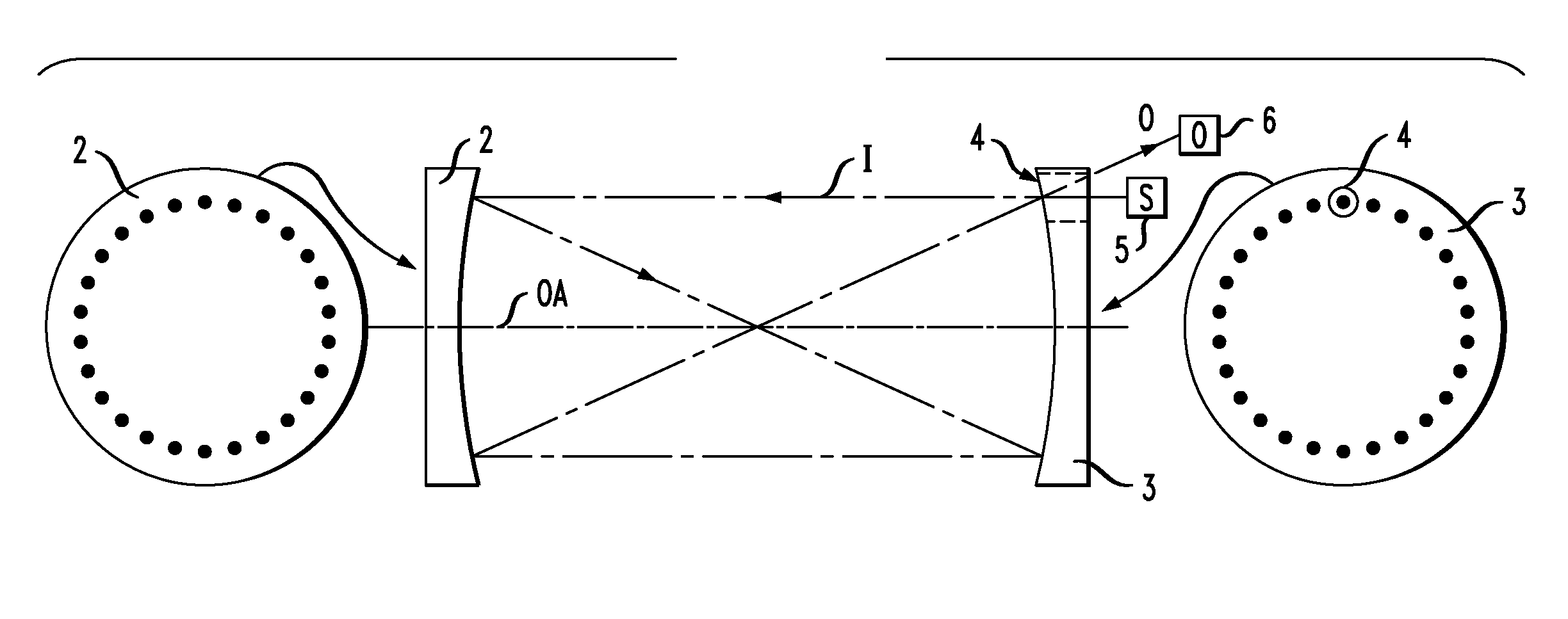
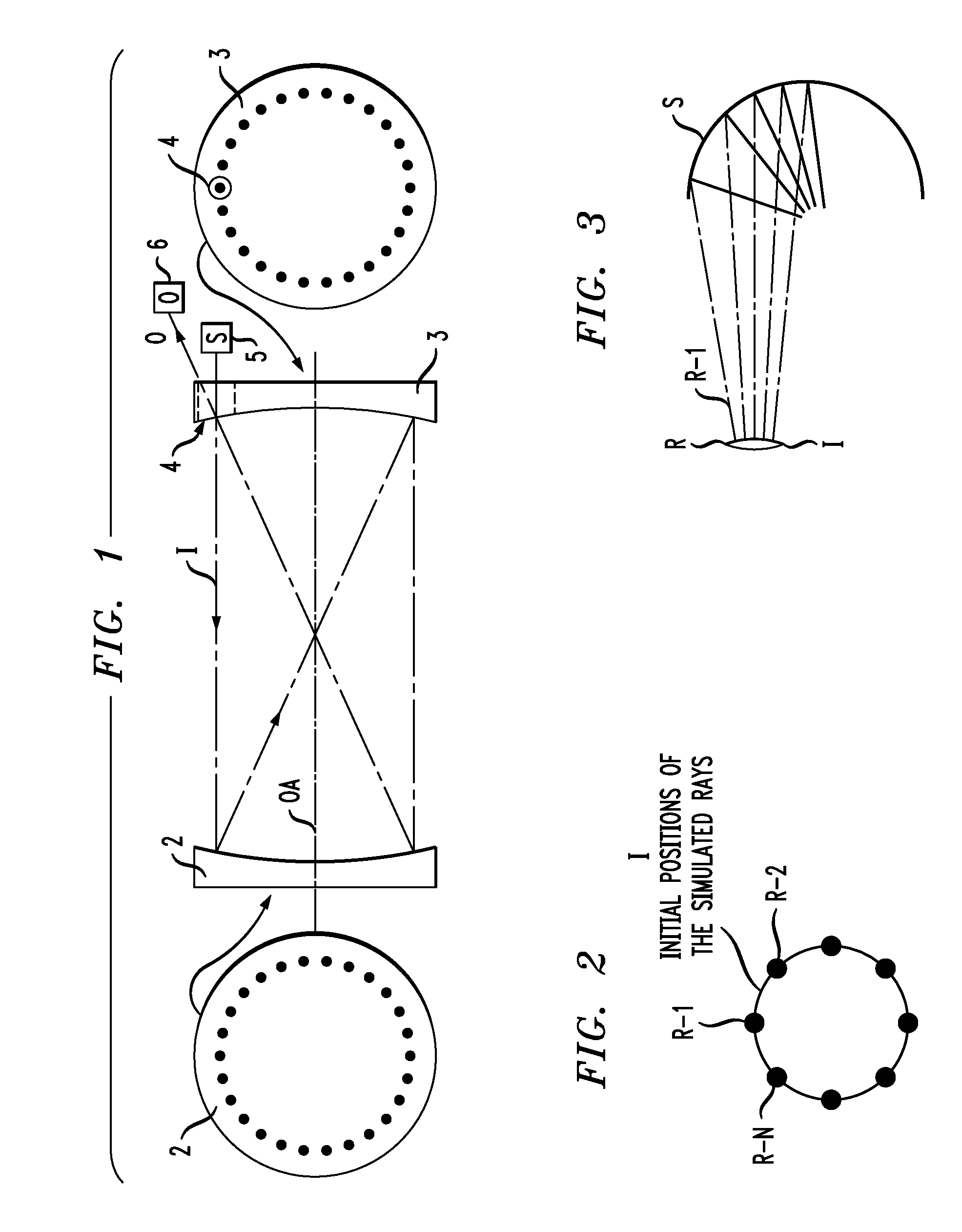
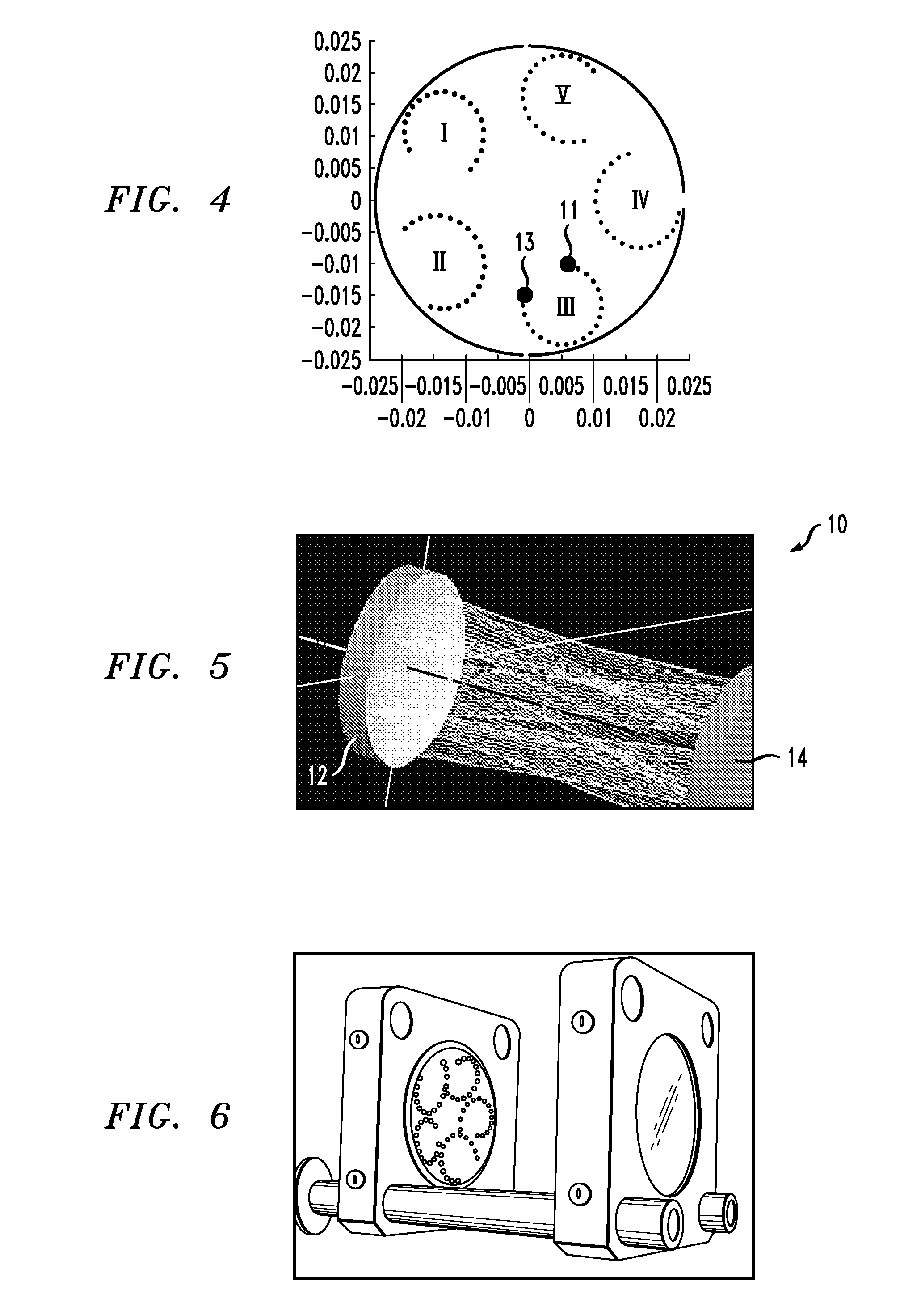
[0033]As described above, it has been found that the prior art matrix-based ray tracing methods can contain significant errors after long paths and multiple reflections as a result of using the paraxial and thin lens approximations, unless the spot pattern is bouncing off surfaces that have a very large radius of curvature. For example, at an angle of 5°, the paraxial approximation of θ≈ sin θ is in error by 0.1%, where the more strongly curved surfaces produce even more oblique reflections. Some correction has been obtained in the past by direct ray tracing of the equation-based solution and adjusting the final configuration to match this more exact ray tracing. However, the paraxial and thin lens approximations are retained for this process as well. The presence of these approximations and lack of equation-based designs that match the actual cell designs is considered to have limited the ability to develop other spot patterns that may otherwise provide viable MPC arrangements. In ...


PUM

PropertyMeasurementUnit
curvatureaaaaaaaaaa
photoacoustic spectroscopyaaaaaaaaaa
Faraday rotation spectroscopyaaaaaaaaaa

Abstract

A technique for designing a multipass optical cell utilizes an iterative artificial intelligence-based optimization process based upon evaluation of direct ray tracing with mirrors simulated as having true spherical surfaces (i.e., defined as a “thick lens”) to identify particular cell configurations that result in creating spot patterns which fill a significant portion of the surface of each mirror without significant spot overlap. This technique allows the use of relatively simple, low-cost spherical mirrors while providing the desired dense spot patterns.

Description

CROSS-REFERENCE TO RELATED APPLICATIONS[0001]This application claims the benefit of U.S. Provisional Application No. 61 / 467,171, filed Mar. 24, 2011 and herein incorporated by reference.TECHNICAL FIELD[0002]The present invention relates to an optical multipass cell (MPC) configuration and, more particularly, to an arrangement that is configured using direct ray tracing techniques to create spot patterns that fill a significant portion of the surface of each mirror without significant beam spot overlap.BACKGROUND OF THE INVENTION[0003]A known and successful system for detecting small quantities of gas in the environment is by the use of absorption spectroscopy. By this technique, a light beam of selected wavelengths that are highly absorbed by the particular gas for which the instrumentation is designed to detect passes through a sample of the gas. The rate of absorption of the light beam is used as an indicator of the level of concentration of the gas in the same. In order to improv...

Claims


Application Information

Patent Timeline
Patent Type & Authority Applications(United States)
IPC IPC(8): G01N21/59G01J3/46G02B5/08
CPCG02B5/10G02B7/182G01N2021/1704G01N21/1702G01N21/031G01N21/01G01N21/59
Inventor SO, STEPHENTHOMAZY, DAVID
Owner AERIS TECH INC
Why Eureka
Try Eureka