Piston cooling apparatus

a cooling device and piston technology, applied in the direction of engine cooling apparatus, liquid cooling, pistons, etc., can solve the problems of easy damage to so as to improve the cooling efficiency of the piston, increase the flow rate of the cooling fluid, and increase the amount of oil circulating.

Inactive Publication Date: 2011-08-11
DOOSAN INFRACORE CO LTD
View PDF3 Cites 12 Cited by
  • Summary
  • Abstract
  • Description
  • Claims
  • Application Information

AI Technical Summary

Benefits of technology

[0012]The disclosed embodiments have been made in an effort to provide a piston cooling device that can improve cooing efficiency of a piston.
[0024]In addition, it is possible to minimize separation of the cooling fluid from the inner circumferential surface of the cooling channel, and accordingly, it is possible to further improve the cooling efficiency, by curving the flow guide part and the intake guide part.

Problems solved by technology

The piston, a part for transmitting explosive pressure inside the cylinder to a crankshaft through a connecting rod, is exposed to high-temperature combustion gas as well as high combustion pressure, such that it may be easily damaged, such as fatigue failure or frictional wear due to thermal deformation, and fusion.
As described above, since not only the cooling efficiency of the piston with the oil gallery of the related art is low, but the thermal stress due to a temperature difference is exerted, resulting in the piston and other parts around the piston to be easily damaged.

Method used


Image

  • Piston cooling apparatus
  • Piston cooling apparatus
  • Piston cooling apparatus

Examples


Embodiment Construction

[0033]Hereinafter, a piston cooling device according to an exemplary embodiment of the present invention is described in detail.

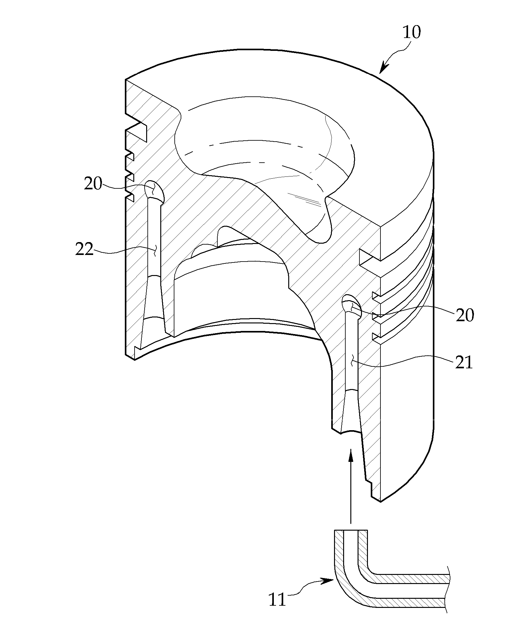
[0034]A piston cooling device according to an exemplary embodiment of the present invention is provided to cool a piston 10 shown in FIG. 4 and implemented in the form of a channel through which cooling fluid can flow in the piston 10.

[0035]The piston cooling device, as shown in FIGS. 5 to 10, includes a cooling channel 20 that has an intake port 21 and an exhaust port 22 and through which cooling fluid, such as oil, flows, a flow guide part 30 that is disposed in the cooling channel 20 and guides the flow of the cooling fluid, and an intake guide unit 40 that guides the cooling fluid, which flows inside through the intake port 21, into the cooling channel 20.

[0036]The cooling channel 20 is a space through which the cooling fluid that cools the piston 10 flows and is formed in a ring shape in the piston 10. However, the shape of the cooling channel 20 may b...


PUM


Abstract

The present invention relates to a piston cooling device for cooling a piston. The piston cooling device according to an exemplary embodiment of the present invention includes: a cooling channel that is formed in a piston such that cooling fluid flows, and communicates with an intake port through which cooling fluid flows inside from the outside at a point and with an exhaust port through which the cooling fluid is discharged outside at another point; and a flow guide part that is formed in the cooling channel and guides the cooling fluid, which flows in the cooling channel through the intake port when the piston moves up or down, to flow to the exhaust port through the cooling channel.

Description

CROSS-REFERENCE TO RELATED APPLICATIONS[0001]This application is a Section 371 National Stage Application of International Application No. PCT / KR2009 / 006070, filed Oct. 21, 2009 and published as WO2010 / 047518 on Apr. 29, 2010 not in English.FIELD OF THE DISCLOSURE[0002]The present invention relates to a piston cooling device for cooling a piston reciprocating in a cylinder of an internal combustion engine, such as an engine, and more particularly, to a piston cooling device that cools a piston by circulating cooling fluid in the piston.BACKGROUND OF THE DISCLOSURE[0003]In general, the engines used for vehicles or construction equipment include a cylinder and a piston that reciprocates inside the cylinder. The piston, a part for transmitting explosive pressure inside the cylinder to a crankshaft through a connecting rod, is exposed to high-temperature combustion gas as well as high combustion pressure, such that it may be easily damaged, such as fatigue failure or frictional wear due...

Claims


Application Information

Patent Timeline
Patent Type & Authority Applications(United States)
IPC IPC(8): F01P1/04
CPCF02F3/22F02F3/003F01P3/06F01P3/10F02F3/20
Inventor KIM, WON NYUN
Owner DOOSAN INFRACORE CO LTD
Why Eureka
Try Eureka