Image signal processing unit and electronic still camera

Inactive Publication Date: 2007-07-03
FUJIFILM CORP
View PDF40 Cites 11 Cited by
  • Summary
  • Abstract
  • Description
  • Claims
  • Application Information

AI Technical Summary

Benefits of technology

[0029]According to the present invention, the lens unit, in which the taking lens is arranged in such a way that the optical axis can turn in the direction of depth of the camera, is detachably mounted in the PC card-sized camera body unit which is provided with the image pickup element, the image processing circuit, etc. When the image data are transmitted to the external information processing apparatus, the camera body unit only is inserted into the card slot of the external information processing apparatus. In order to ta

Problems solved by technology

The PC card section of the electronic still camera has the same thickness as the PC card, but the image input device including the taking lens is bulky, and the camera as a whole is

Method used


Image

  • Image signal processing unit and electronic still camera
  • Image signal processing unit and electronic still camera
  • Image signal processing unit and electronic still camera

Examples


first embodiment

[0107]FIG. 4 is a view illustrating the electronic still camera according to the present invention, and FIG. 5 is a block diagram illustrating the inner construction of the electronic still camera shown in FIG. 3.

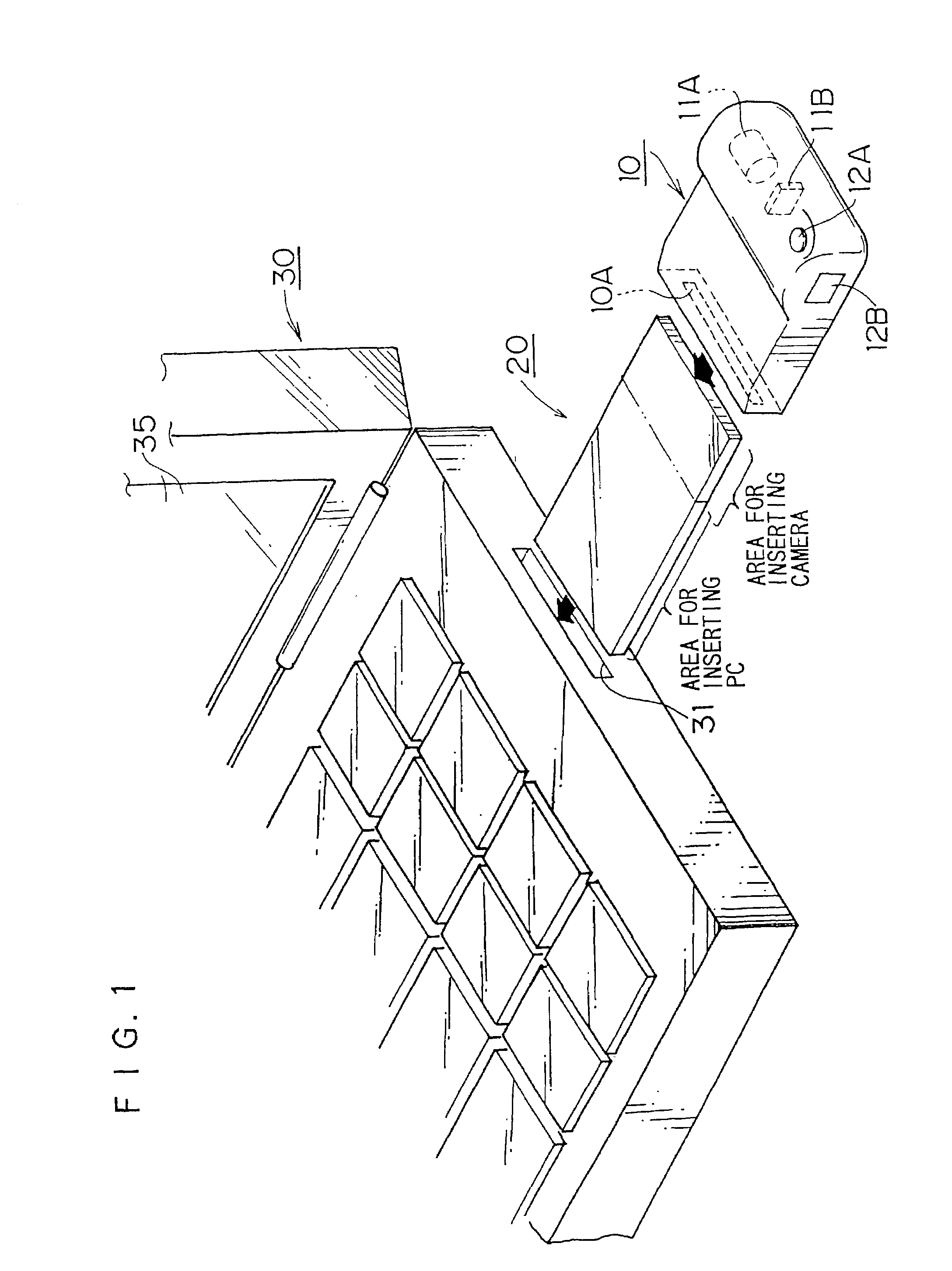
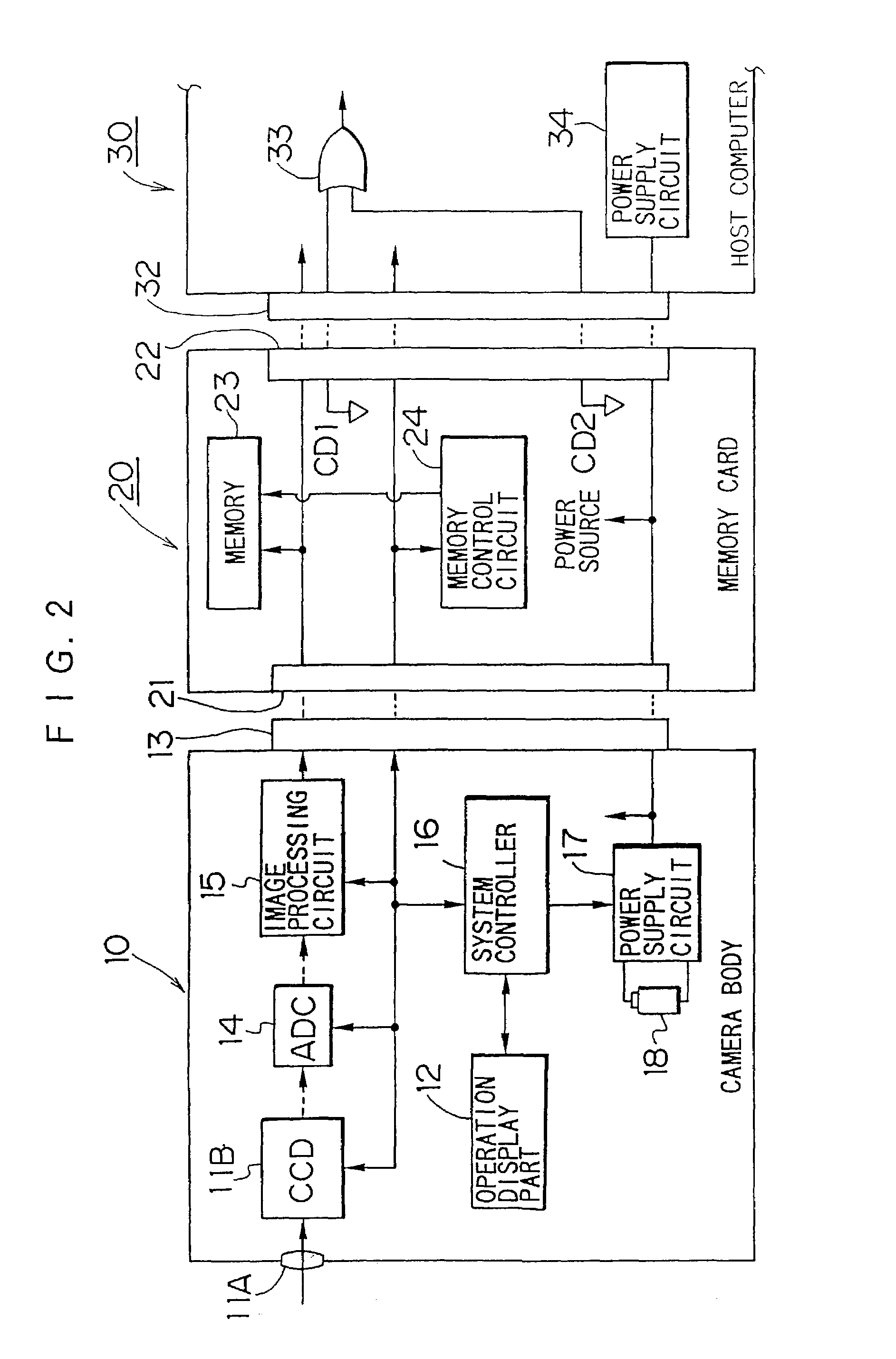
[0108]As shown in FIGS. 4 and 5, the electronic still camera consists of an image pick-up unit 110 and an IC card portion 130 which is in the same form as a memory card such as, for example, a PCMCIA card.

[0109]The image pick-up unit 110 is provided at its side with a card slot 111 as shown in FIG. 4; the IC card portion 130 can be detachable via the card slot 111. As shown in FIG. 5, the image pick-up unit 110 consists of a taking lens 112, a CCD 113, a connector 121 in the card slot 111, a shutter button 123, and a battery 124. The reference numeral 126 in FIG. 4 is a finder.

[0110]On the other hand, as shown in FIG. 5, the IC card portion 130 consists of a connector 131 (the second connector) which is connected to a connector 121 (the first connector) of the image pick-up...

second embodiment

[0119]FIG. 6 is a view illustrating the electronic still camera according to the present invention. The similar parts as shown in FIGS. 4 and 5 have the same reference numerals and alphabets, and the detailed explanation for them is omitted. The electronic still camera in FIG. 6 has the same circuit construction as the one in FIG. 5.

[0120]In the second embodiment shown in FIG. 6, a recessed portion 166 for containing the small-sized memory card 162 instead of the slot 160 provided on the diagonal side of the IC card portion 130 is formed on the surface side of the IC card portion 130. A cover 168 of the recessed portion 166 can be freely opened and closed via a hinge 170. When the cover 168 is closed the memory card 162 can be contained in the recessed portion 166. The recessed portion 166 can contain the small-sized memory card 162 which is 0.78 mm thick, and is provided a connector (an armature; the fourth connector) 136.

[0121]Therefore, when the small-sized memory card 162 is con...

third embodiment

[0122]FIG. 7 is a view illustrating the electronic still camera according to the present invention. The similar parts shown in FIGS. 4 and 5 have the same reference numerals, and a detailed explanation for them is omitted.

[0123]In the embodiments in FIGS. 4 and 6, the IC card portion 130 is constructed as being freely detachable with the image pick-up part 110; however, in the embodiment in FIG. 7, the IC card portion 130 is integrally constructed with the image pick-up part 110, and the connectors 121, 131 are not required. Like the embodiment in FIG. 4, in the embodiment in FIG. 7, the small-sized memory card 162 is inserted to be freely detachable into the slot 160 formed on the diagonal side of the IC card portion 130. Moreover, in the embodiment in FIG. 7, the recessed portion 166 which has the connector 136 at the surface side of the IC card portion 130 may be provided like the embodiment in FIG. 6.


PUM


Abstract

An electronic still camera which is able to substantially lessen the amount of trouble of inserting and drawing a PC card during photographing or when image data are transferred to a host computer such as a laptop computer, and which is able to increase the number of photographing. The electronic still camera has the PC card which is inserted into or drawn out from a camera body, which has the same shape as the PC card. The PC card or the camera body shaped like the PC card is inserted into a PC card slot of the host computer to transmit and receive the image data, etc. A camera casing including a taking lens, etc. is mounted in the camera body shaped like the PC card, and a sheet-like battery is provided in the camera body. The taking lens is capable of projecting from and retracting into the camera body.

Description

[0001]This application is a divisional of application Ser. No. 09 / 822,197 now U.S. Pat. No. 6,525,767 filed Apr. 2, 2001, which was a divisional of application Ser. No. 08 / 942,366, filed on Oct. 2, 1997, now U.S. Pat. No. 6,256,063 issued on Jul. 3, 2001, the entire contents of both prior applications are hereby incorporated by reference and for which priority is claimed under 35 U.S.C. § 120; and this application claims priority of Application No. 8-262144, 8-272209, 8-272210, 8-275035, 8-291973, 9-50391, 9-50392, 9-55197, and 9-70039 filed in Japan on Oct. 2, 96, Oct. 15, 96, Oct. 15, 96, Oct. 15, 96, Oct. 17, 96, Nov. 1, 96, Mar. 5, 97, Mar. 5, 97, Mar. 10, 97 and Mar. 24, 97, respectively under 35 U.S.C. § 119.BACKGROUND OF THE INVENTION[0002]1. Field of the Invention[0003]The present invention relates generally to an electronic still camera and an image signal processing apparatus, and more particularly to an electronic still camera which uses a memory card, and an image signal...

Claims


Application Information

Patent Timeline
IPC IPC(8): H04N5/76H04N1/00H04N5/225H04N5/232
CPCH04N1/00236H04N1/00241H04N1/2158H04N5/2251H04N5/232H04N1/00204H04N2101/00H04N2201/0034H04N2201/0051H04N23/531H04N23/55H04N23/65H04N23/63
Inventor SAITO, OSAMUMISAWA, ATSUSHIMISAWA, TAKESHI
Owner FUJIFILM CORP
Why Eureka
Try Eureka