
Condensation-reducing incubation cover

Inactive Publication Date: 2014-04-24
QIAGEN GAITHERSBURG
View PDF4 Cites 19 Cited by
  • Summary
  • Abstract
  • Description
  • Claims
  • Application Information

AI Technical Summary

Benefits of technology

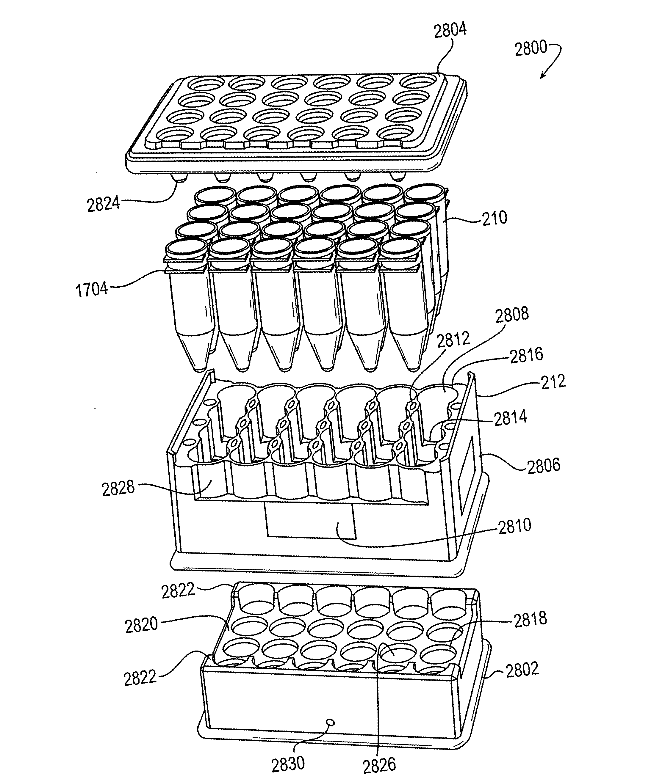
The patent describes a cover for a collection of sample tubes used in an incubation process. The cover has an upper panel and protrusions that extend downward from the panel. Each protrusion has two seals: an upper conical section and a cylindrical section. The conical section tapers from a larger diameter to a smaller diameter to create a seal with the sample tube. The cylindrical section has a narrower diameter to create a capillary seal with the sample tube when liquid is present. This cover design helps to prevent contamination and maintain the integrity of the sample during incubation.

Problems solved by technology

In many cases, it can be difficult, burdensome, uncomfortable, or even painful to obtain a sample from the subject, and therefore a high value is placed on taking great care with handling and testing the sample to prevent the need for multiple sample collection procedures.
Even if no pellet is detected, the protocol continues, a pellet that is too small to see can still provide a positive test result (however, if there is no visible pellet, a negative test result might be dismissed as a false negative, and such an indeterminate result may require further testing).
In some cases, the manual steps comprising the protocol may not be readily performed by an automated system.
These processes may not be readily-amenable to automated processing of multiple samples.
Furthermore, where the protocol is regulated, it may be difficult to simulate the manual steps in an automated environment.
Still further, even where a manual protocol is converted to an automated process, there may remain a question of whether the two processes are truly comparable, as numerous innocuous-seeming deviations from the protocol that are required by the automated process may, in fact, substantially affect the final results.
The conversion of manual protocols to automated processes can present many challenges, and numerous unforeseen issues often arise.

Method used


Image

  • Condensation-reducing incubation cover
  • Condensation-reducing incubation cover
  • Condensation-reducing incubation cover

Examples


first processing example

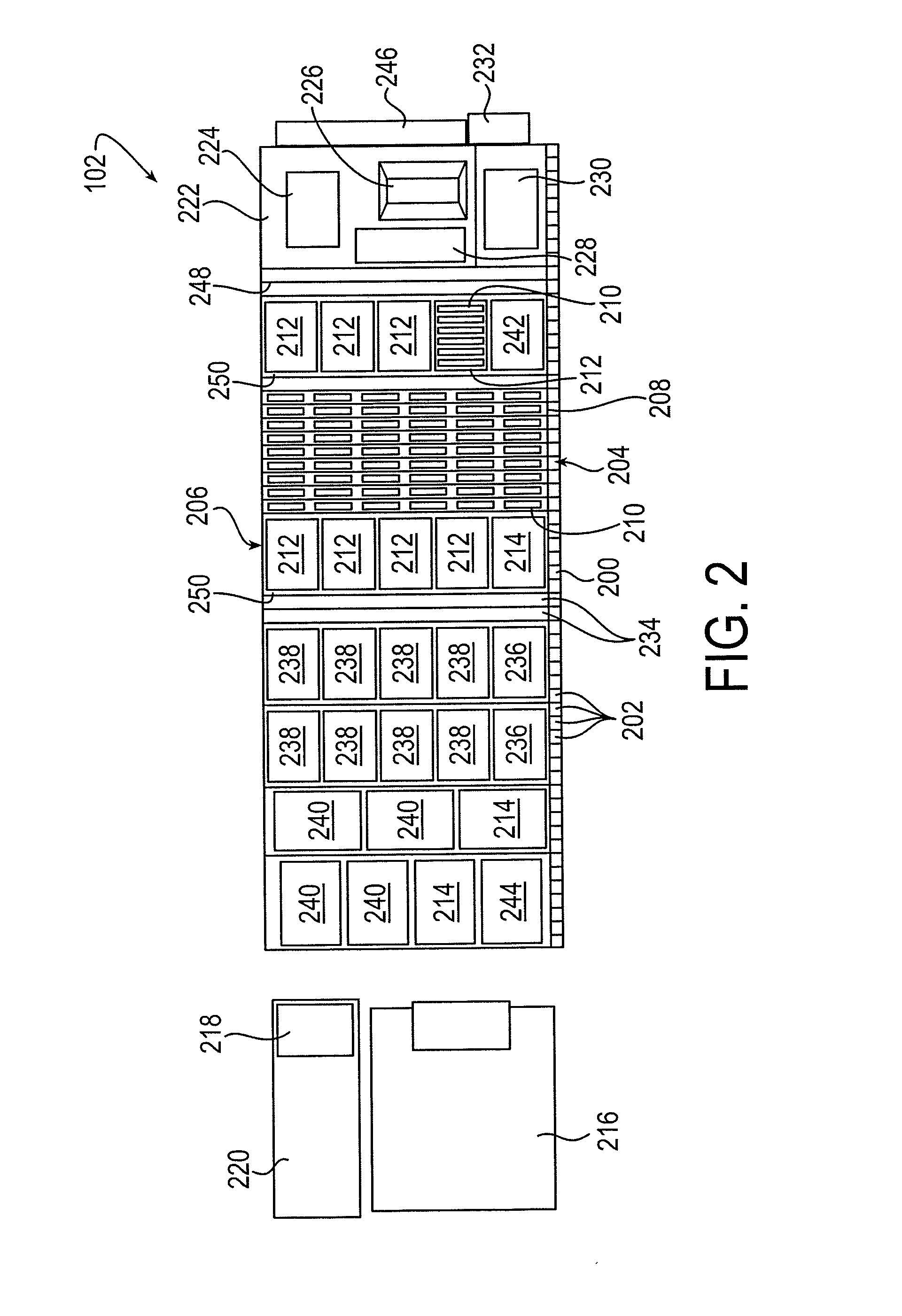
[0287]An embodiment of a sample processing module assembled according to the embodiment of FIG. 2 was used to process human tissue samples according to the process described with reference to FIG. 3. Specifically, samples in vials of PreservCyt® media were manually mixed and dispensed into separate tubes of a four-tube tube strip. Each tube in the strip was a 6 milliliter tubes with conventional Sarstedt cone geometry. The tube strips were manually loaded into the processing module. At this point, automated processing began. First, the processing module loaded each tube strip into a tube strip holder that holds six tube strips. A Hamilton pipettor loaded with 5 milliliter tips dispensed 400 micro-liters of HC2 Sample Conversion Buffer into each tube. Next, the tube strip holder (including the tube strips and samples) was mixed on a Hamilton orbital shaker operated for 30 seconds at 800 rpm on a 3 millimeter orbit. The tube strip holder (and strips and samples) was then loaded into a...

second processing example

[0288]The process and apparatus described in the First Processing Example were modified by making the following changes. First, the samples were originally provided in SurePath™ media, rather than PreservCyt®. Second, SCB was not dispensed into the tube strip. Third, the pre-centrifuge mixing step (step 310) was not performed. Fourth, the centrifuge step (step 312) was conducted at a somewhat lower gravitational load, and for approximately ten minutes. Fifth, the samples were decanted by rotating the tube strip in a first direction to an angle of 210° (measured downwards from vertical), pausing for approximately 0.5 to 1 second, and then continuing to rotate the tube strip in the first direction until the tube strip was upright (i.e., a full 360° rotation with a 0.5 to 1 second pause at 210°). And sixth, the incubation step (step 326) was conducted for approximately 90 minutes, with some variation in the mixing process. The remaining steps and procedures were identical to those desc...

third processing example

[0289]An embodiment of a sample processing module assembled according to the embodiment of FIG. 4 was used to process human tissue samples according to the process described with reference to FIGS. 5 and 3. In this example, individual samples in PreservCyt® vials were vortexed according to the conventional manual HC2 procedure, and then manually loaded into vial racks. The loaded vial racks were loaded into the processing module, and automated processing began. The automated process began by operating Hamilton pipettors loaded with 5 milliliter pipette tips to hydraulically mix the contents of each sample vial, and pipette 4 milliliters of each mixed sample solution to a respective tube in a four-tube tube strip, such as the tube strip described in the First Processing Example. From here, the processing module continued processing the samples as described above in the automated processing steps of the First Processing Example.


PUM


Abstract

A cover for covering an array of sample tubes during an incubation process. The cover has an upper panel and protrusions extending downward from the upper panel. Each protrusion has an upper seal and a lower seal. The upper seal includes a first conical section that tapers from a first diameter that is larger than the inside diameter of a corresponding sample tube to a second diameter that is smaller than the inside diameter of the corresponding sample tube. The lower seal includes a cylindrical section extending downward from the bottom of the first conical section. The cylindrical section has a diameter selected to create a capillary seal, in the presence of a liquid, between the cylindrical section and an adjacent portion of an inner wall of the corresponding sample tube.

Description

BACKGROUND OF THE INVENTION[0001]1. Field of the Invention[0002]The present invention relates to automated systems and methods for preparing samples, such as biological samples. Particular exemplary embodiments relate to processing samples used to determine the presence or absence of human papillomavirus or other conditions.[0003]2. Description of the Related Art[0004]A wide variety of processing protocols are used in many different fields of art. Processing protocols are created and followed to help make sure similar items are processed the same way. The use of protocols helps provide consistent processing results and, where the results are not consistent, ensures that the differences are not attributable to variances caused by the processing itself.[0005]Processing protocols are particularly important in the field of analytical biological science, in which biological samples are taken from a subject and processed to diagnose medical conditions, such as the presence or absence of a...

Claims


Application Information

Patent Timeline
IPC IPC(8): B01L99/00
CPCB01L99/00B01L3/50825B01L3/50853B01L3/50855B01L2200/0689B01L2200/142B01L2300/047B01L2300/0829B01L2300/0858B01L2300/1805G01N1/2813G01N35/026
Inventor EDENS, CARL THEODORELEONARD, ANDREWJUNGHEIM, BERTHAVIERNIK, PETERCUI, BOWEN
Owner QIAGEN GAITHERSBURG
Learn More