Splitter

a technology of splitter and wlan, which is applied in the direction of impedence networks, transmission, electrical equipment, etc., can solve the problems of increasing the number of components and the cost, unable to separate a wlan signal from a band 7 signal, and difficulty in achieving high steepness in the attenuated region adjacent to so as to achieve effective steepness in the vicinity of the wlan pass band, the effect of preventing or significantly reducing

Active Publication Date: 2014-04-24
MURATA MFG CO LTD
View PDF10 Cites 17 Cited by
  • Summary
  • Abstract
  • Description
  • Claims
  • Application Information

AI Technical Summary

Benefits of technology

[0013]Preferred embodiments of the present invention provide a splitter that is provided at a low cost without having an increased number of components and that is capable of effectively attaining high steepness of a filter characteristic in an attenuated region adjacent to the pass band of a band pass filter connected to an antenna terminal.
[0017]In a certain specific aspect of a splitter according to a preferred embodiment of the present invention, the high pass filter includes at least one elastic wave resonator provided in a series arm that links the input terminal and the output terminal of the high pass filter, and at least one inductance element provided in a parallel arm that links the series arm and a ground potential. A filter characteristic of the high pass filter is obtained from a capacitance component of the elastic wave resonator and an inductance of the inductance element. In addition, a characteristic of the notch filter is obtained from an anti-resonant frequency of the elastic wave resonator. Thus, a trap, that is, a stop band, is included in the frequency characteristic. In this case, the steepness of an attenuated region of the second band pass filter is more effectively made high with a small number of components.
[0019]In addition, in another specific aspect of a splitter according to a preferred embodiment of the present invention, the high pass filter includes first and second elastic wave resonators arranged in the series arm, a first inductance element arranged in a first parallel arm that is connected between the input terminal and a ground potential, and a second inductance element arranged in a second parallel arm connected between the output terminal and the ground potential. In this case, impedance matching is easily obtained by the inductance elements arranged in the parallel arms. In addition, a surge withstand voltage characteristic is also made high.
[0021]In yet another specific aspect of a splitter according to a preferred embodiment of the present invention, the first pass band of the first band pass filter includes a transmission frequency of GPS or GLONASS, and the third pass band of the second band pass filter includes a 2.4 GHz band WLAN transmission frequency and the stop band is a Band 7 or Band 40 UMTS transmission frequency band. In this case, steepness in the vicinity of the WLAN pass band is effectively made high in a configuration including the first band pass filter corresponding to GPS or GLONASS and the second band pass filter corresponding to WLAN. Therefore, the influence of Band 7 or Band 40 is prevented or significantly reduced and selectivity for a WLAN signal is made high.
[0022]In a splitter according to various preferred embodiments of the present invention, the high pass filter also functions as a notch filter and therefore a wanted signal is extracted while interference from an unwanted signal is prevented or significantly reduced. Moreover, an increase in the number of components is prevented due to the high pass filter also functioning as a notch filter.

Problems solved by technology

Therefore, it is not possible to separate a WLAN signal from a Band 7 signal with the high pass filter 1006.
Moreover, even if such a band pass filter 1008 is connected, it is difficult to attain high steepness in an attenuated region adjacent to the WLAN pass band.
Therefore, there has been a problem in that the number of components and the cost are increased.
However, since a switch is necessary, increases in size and cost are incurred.

Method used


Image

  • Splitter
  • Splitter
  • Splitter

Examples


Embodiment Construction

[0029]Hereafter, the present invention will be made clearer by describing specific preferred embodiments of the present invention while referring to the drawings.

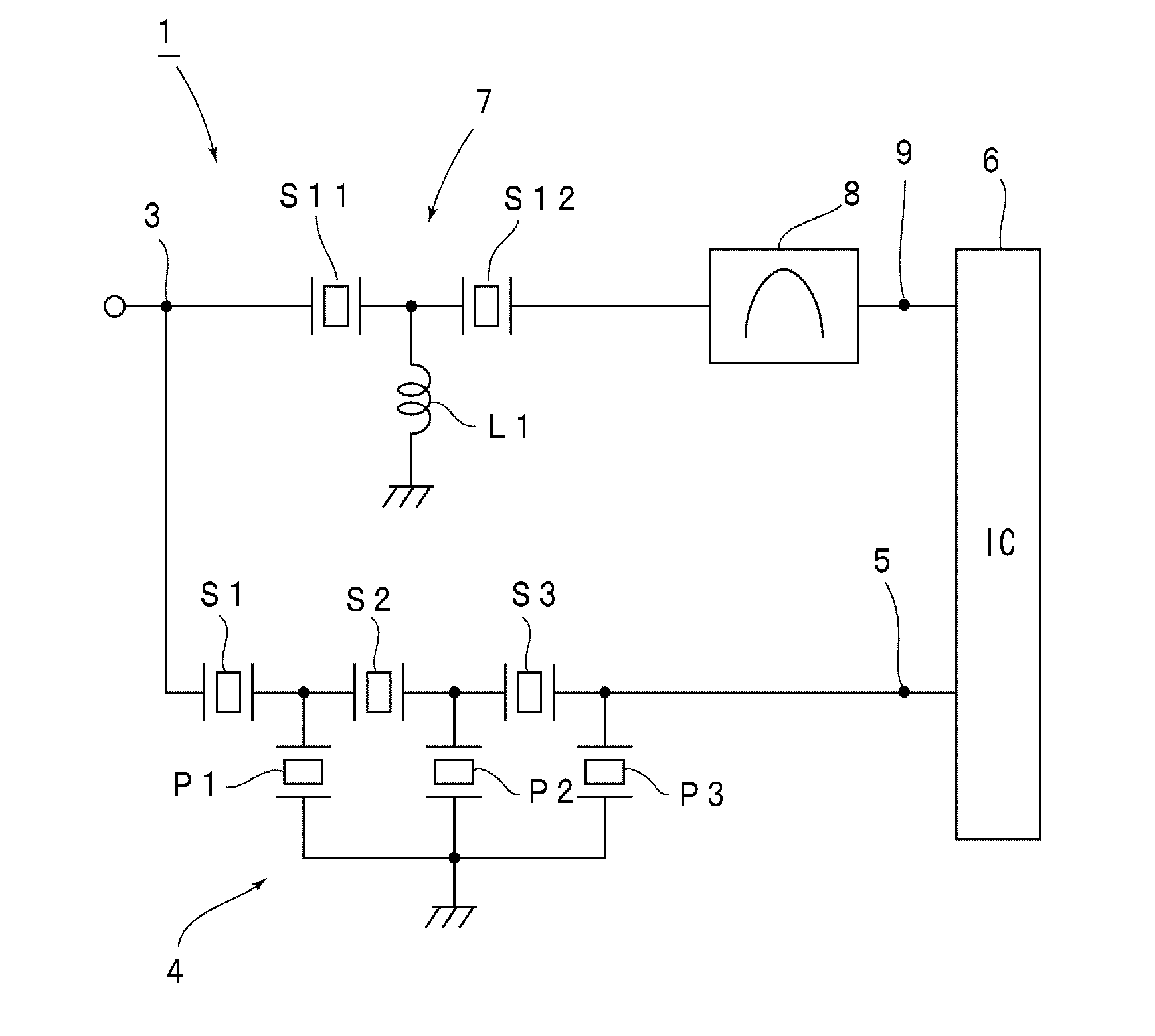
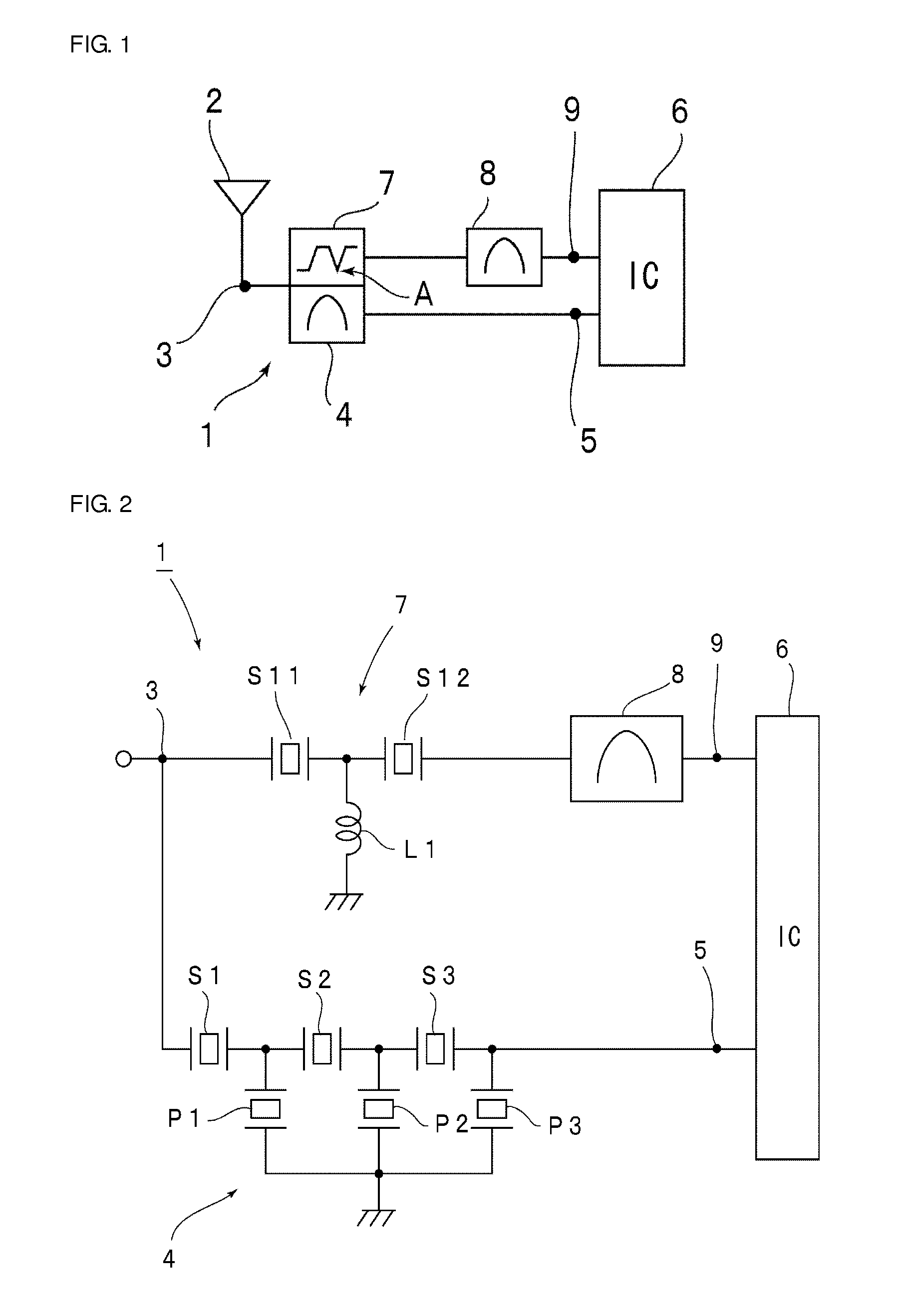
[0030]FIG. 1 is an outline structural diagram for explaining a splitter according to a first preferred embodiment of the present invention. A splitter 1 includes an antenna terminal 3 that is connected to an antenna of a cellular phone. The splitter 1 extracts a GPS signal and a WLAN signal. In the splitter 1, the GPS pass band preferably is around 1.5 GHz to 1.6 GHz, for example. On the other hand, the WLAN pass band preferably is around 2.4 GHz in IEEE802.11b, IEEE802.11g and IEEE802.11n. Incidentally, the UMTS Band 7 transmission frequency band is close to the high-frequency side of the 2.4 GHz band WLAN pass band. The Band 7 transmission frequency band is 2.5 GHz to 2.69 GHz. Therefore, it is necessary that a Band 7 signal be sufficiently attenuated on the on the side where a WLAN signal is to be extracted.

[0031]The spl...


PUM


Abstract

In a splitter, a first band pass filter is connected between an antenna terminal and a first terminal, a high pass filter and a second band pass filter are connected between the antenna terminal and a second terminal, a pass band of the second band pass filter is higher than a pass band of the first band pass filter, a cut off frequency of the high pass filter is located closer to the high-frequency side than the pass band of the first band pass filter, the pass band of the second band pass filter is located closer to the high-frequency side than the cut off frequency, and the high pass filter also functions as a notch filter having an anti-resonant frequency in a transition region such that the steepness of the transition region between the pass band of the second band pass filter and the attenuated band is high.

Description

BACKGROUND OF THE INVENTION[0001]1. Field of the Invention[0002]The present invention relates to splitters that preferably are, for example, used in cellular phones and more specifically relates to splitters in which a first band pass filter is connected to an antenna terminal and a second band pass filter is connected to the antenna terminal and has a pass band in a higher frequency range than the first band pass filter.[0003]2. Description of the Related Art[0004]In recent years, in cellular phones, signals have been transmitted and received using many communication schemes. Consequently, a splitter is connected to an antenna terminal.[0005]For example, a splitter, which is illustrated in FIG. 5, is disclosed in International Publication No. WO 2005 / 088833. A splitter 1001 has an antenna terminal 1002. A band pass filter 1004, which has a relatively low pass band, is connected to the antenna terminal 1002 via a matching circuit 1003. The band pass filter 1004 is formed of a surfac...

Claims


Application Information

Patent Timeline
Patent Type & Authority Applications(United States)
IPC IPC(8): H04B1/10
CPCH04B1/1036H03H9/6483H03H9/725
Inventor YAMAZAKI, SUNAO
Owner MURATA MFG CO LTD
Why Eureka
Try Eureka