Magnetorheological fluid shock absorber

Inactive Publication Date: 2014-05-01
KYB CORP
View PDF11 Cites 2 Cited by
  • Summary
  • Abstract
  • Description
  • Claims
  • Application Information

AI Technical Summary

Benefits of technology

[0005]This invention has been designed in consideration of the problems described above, and an object thereof is to provide a magnetorheological fluid shock absorber in which

Problems solved by technology

Further, the magnetorheological fluid shock absorber is structured such that a periphery of a magnetic field generation device is covered by the magnetorheological fluid, a

Method used


Image

  • Magnetorheological fluid shock absorber
  • Magnetorheological fluid shock absorber
  • Magnetorheological fluid shock absorber

Examples


first embodiment

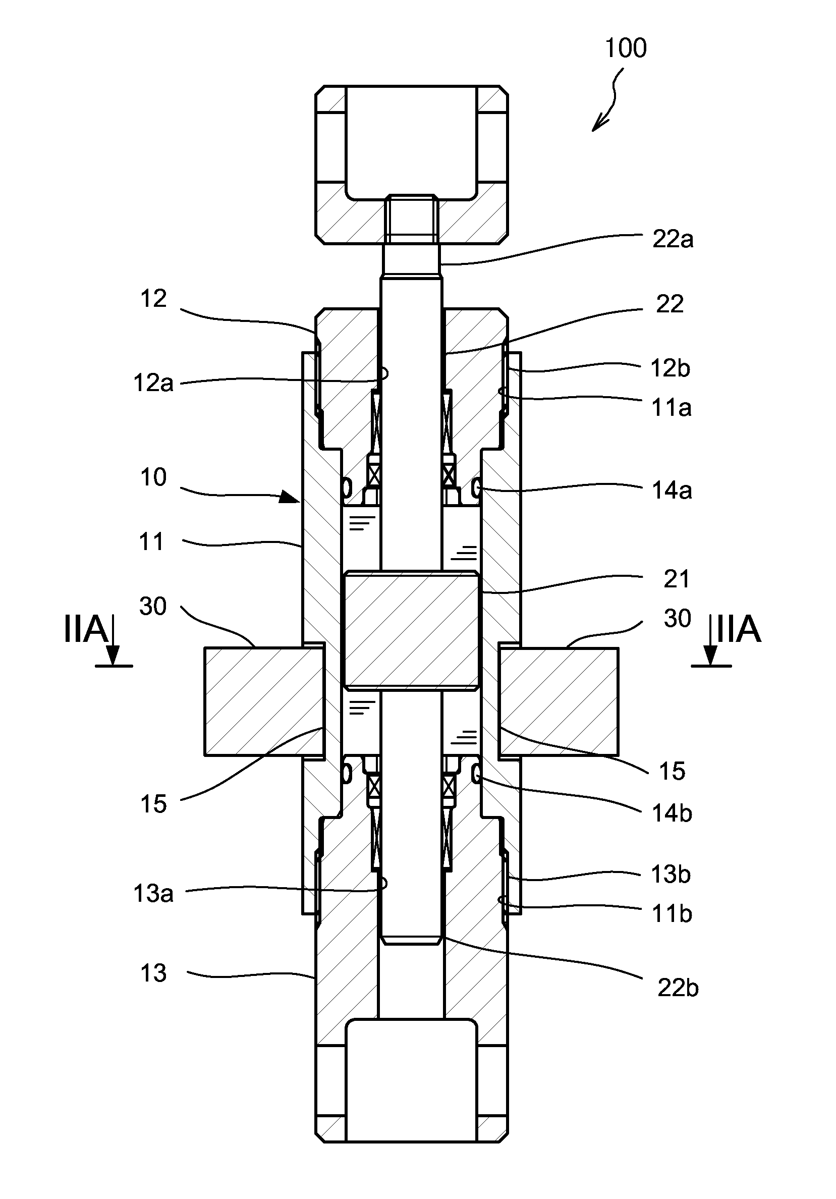
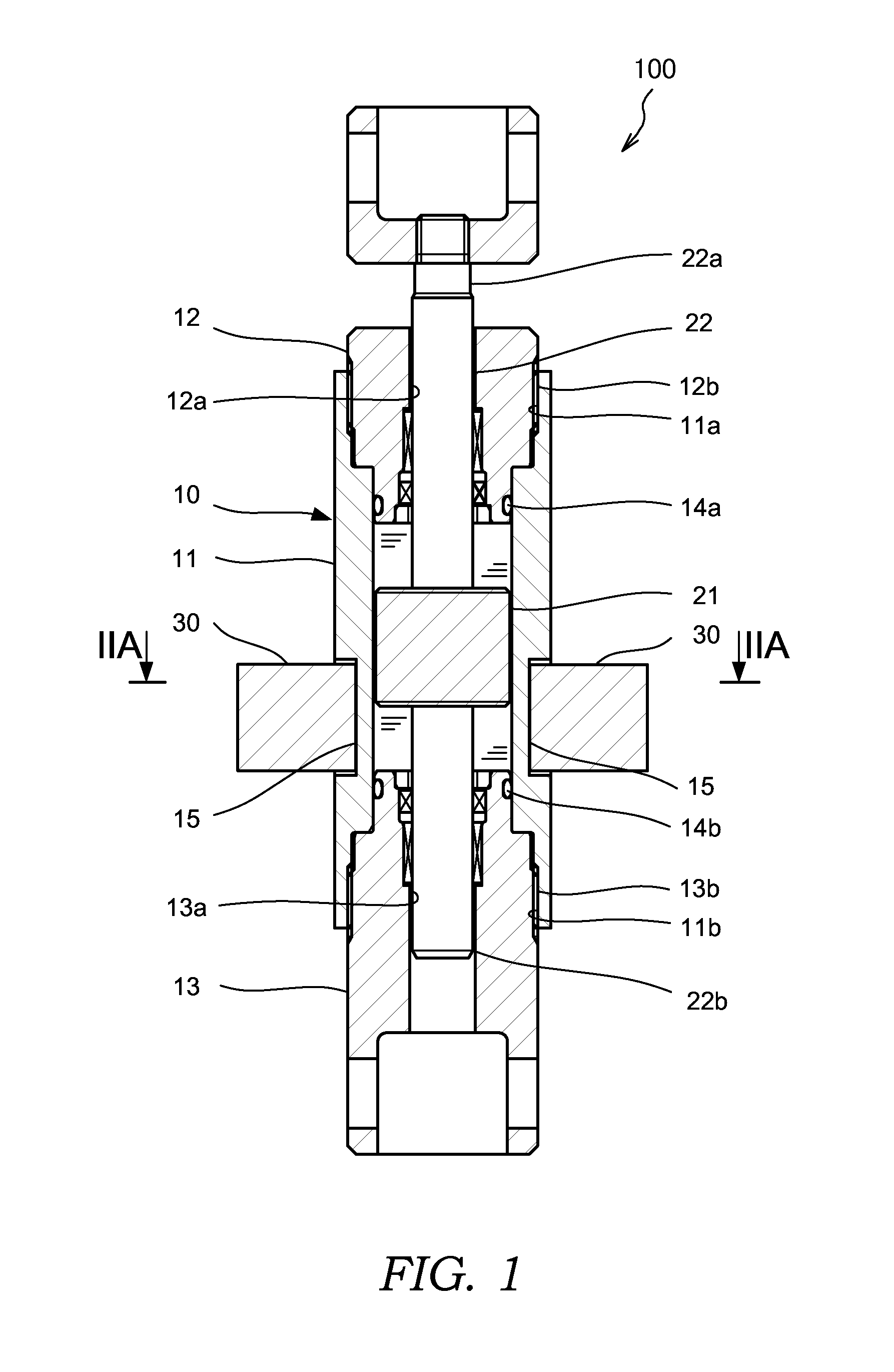
[0017]First, referring to FIG. 1, an overall configuration of a magnetorheological fluid shock absorber 100 according to this invention will be described. FIG. 1 is a sectional view of the magnetorheological fluid shock absorber 100.

[0018]The magnetorheological fluid shock absorber 100 is a damper in which a damping coefficient relative to a force applied in an axial direction can be varied using a magnetorheological fluid that is varied in viscosity by an action of a magnetic field. The magnetorheological fluid shock absorber 100 is formed such that the damping coefficient thereof varies proportionally in accordance with a stroke amount of a piston 21.

[0019]The magnetorheological fluid shock absorber 100 includes a tubular cylinder 10 having a magnetorheological fluid sealed into an inner periphery thereof, the piston 21, which is disposed in the cylinder 10 to be free to slide in an axial direction of the cylinder 10, a piston rod 22 to which the piston 21 is connected, and a magn...

second embodiment

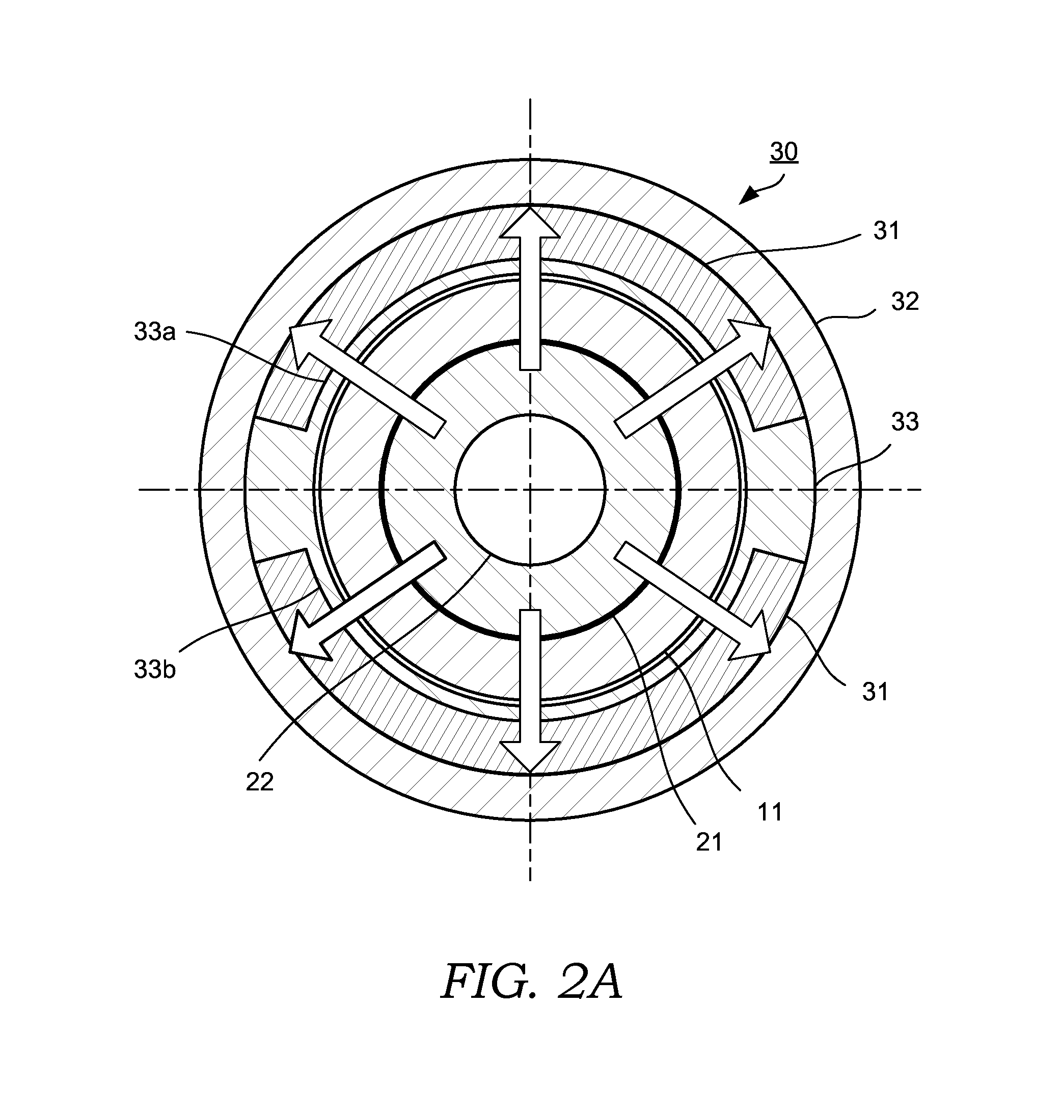
[0061]In the second embodiment, the permanent magnets 31 are magnetized by groups of magnetic poles in the radial direction, as shown in FIG. 4B. In the example shown in FIG. 4B, one of the permanent magnets 31 is magnetized to an N pole on the inner peripheral surface 31a side and an S pole on the outer peripheral surface 31b side. The other permanent magnet 31 is magnetized to an S pole on the inner peripheral surface 31a side and an N pole on the outer peripheral surface 31b side. The pair of permanent magnets 31 are disposed in the magnet portion 30 such that opposite magnetic poles oppose each other about the central axis of the cylinder 10. In other words, the magnetic poles of the pair of permanent magnets 31 differ from each other.

[0062]With this configuration, the magnet portion 30 generates a magnetic field in the direction of an arrow shown in FIG. 4A. In other words, by disposing the pair of permanent magnets 31 so that opposite magnetic poles oppose each other, magnetic...


PUM


Abstract

A magnetorheological fluid shock absorber that uses a magnetorheological fluid having a viscosity includes: a tubular cylinder formed from a non-magnetic material and having the magnetorheological fluid sealed into an inner periphery thereof; a piston formed from a non-magnetic material and disposed in the cylinder to be free to slide at an interval, through which the magnetorheological fluid can pass, relative to the inner periphery of the cylinder; a piston rod to which the piston is connected; and a magnet portion attached to the cylinder in order to apply a magnetic field to an interior of the cylinder. The magnet portion includes a permanent magnet having an inner peripheral shape that aligns with an outer periphery of the cylinder; and a ring member formed from a magnetic material and disposed on an outer peripheral side of the permanent magnet.

Description

TECHNICAL FIELD[0001]This invention relates to a magnetorheological fluid shock absorber that uses a magnetorheological fluid having an apparent viscosity that is varied by an action of a magnetic field.BACKGROUND ART[0002]A damping force of a shock absorber installed in a vehicle such as an automobile may be varied by applying a magnetic field to a flow passage through which a magnetorheological fluid passes in order to vary an apparent viscosity of the magnetorheological fluid.[0003]JP2007-239982A discloses a magnetorheological fluid shock absorber in which a permanent magnet is attached to respective axial direction end portions of a cylinder in which a magnetorheoloigcal fluid is sealed. In this magnetorheological fluid shock absorber, a yoke material is provided on an outer periphery of the cylinder, and a piston and a part of a piston rod are formed from a ferromagnetic material. In this magnetorheological fluid shock absorber, when the piston is positioned in a neutral region...

Claims


Application Information

Patent Timeline
IPC IPC(8): F16F9/53
CPCF16F9/535
Inventor SAITO, KEIJISHIMADA, MIHO
Owner KYB CORP
Why Eureka
Try Eureka