
D-ring implementation in skewed rotor assembly

a technology of rotor assembly and d-ring, which is applied in the field of implementation of sensorless electric machines, can solve the problems of ipm machines suffering from both a manufacturing and a technical (i.e., electromechanical) shortcoming, damage to the rotor, the gearbox, and/or the mechanical system(s) connected, etc., and achieves the effect of more efficient manufacturing and more technical efficiency

Active Publication Date: 2014-05-01
WESTINGHOUSE AIR BRAKE TECH CORP
View PDF8 Cites 38 Cited by
  • Summary
  • Abstract
  • Description
  • Claims
  • Application Information

AI Technical Summary

Benefits of technology

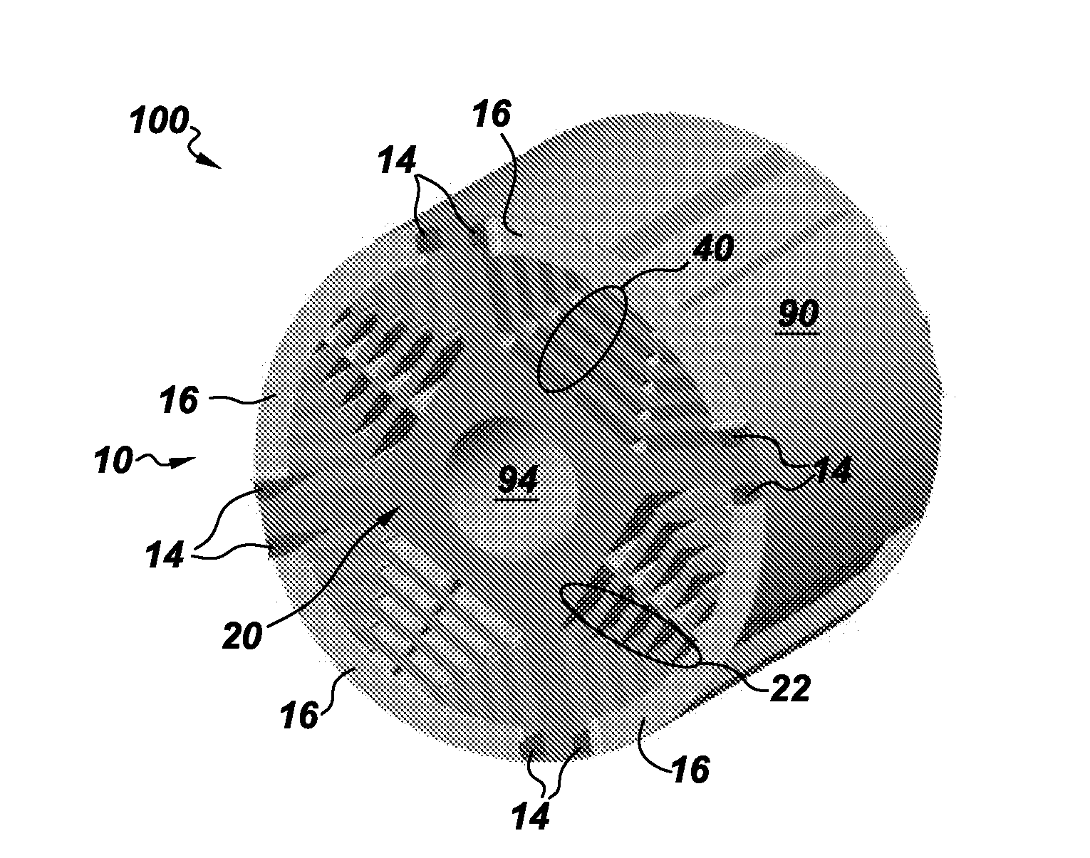
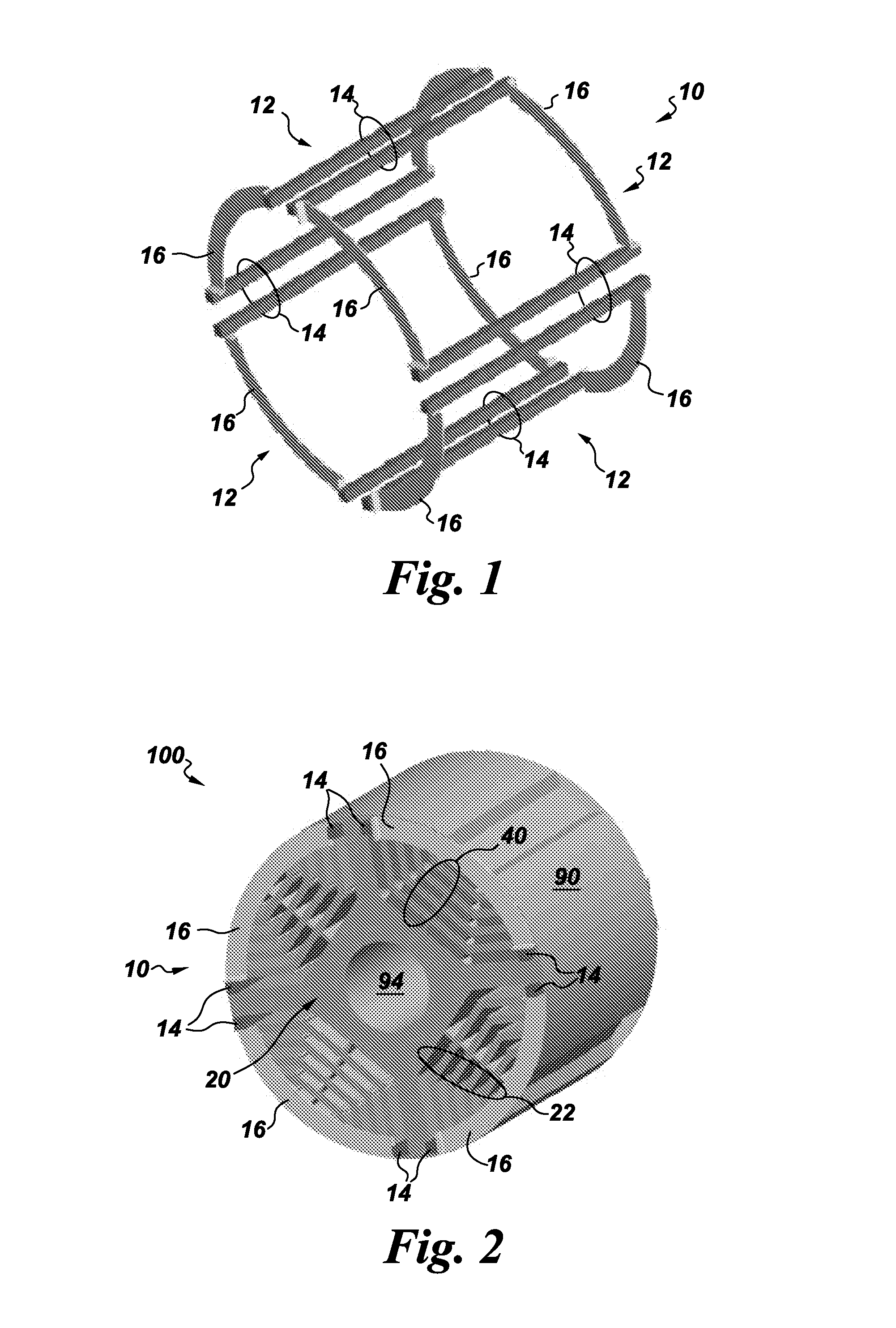
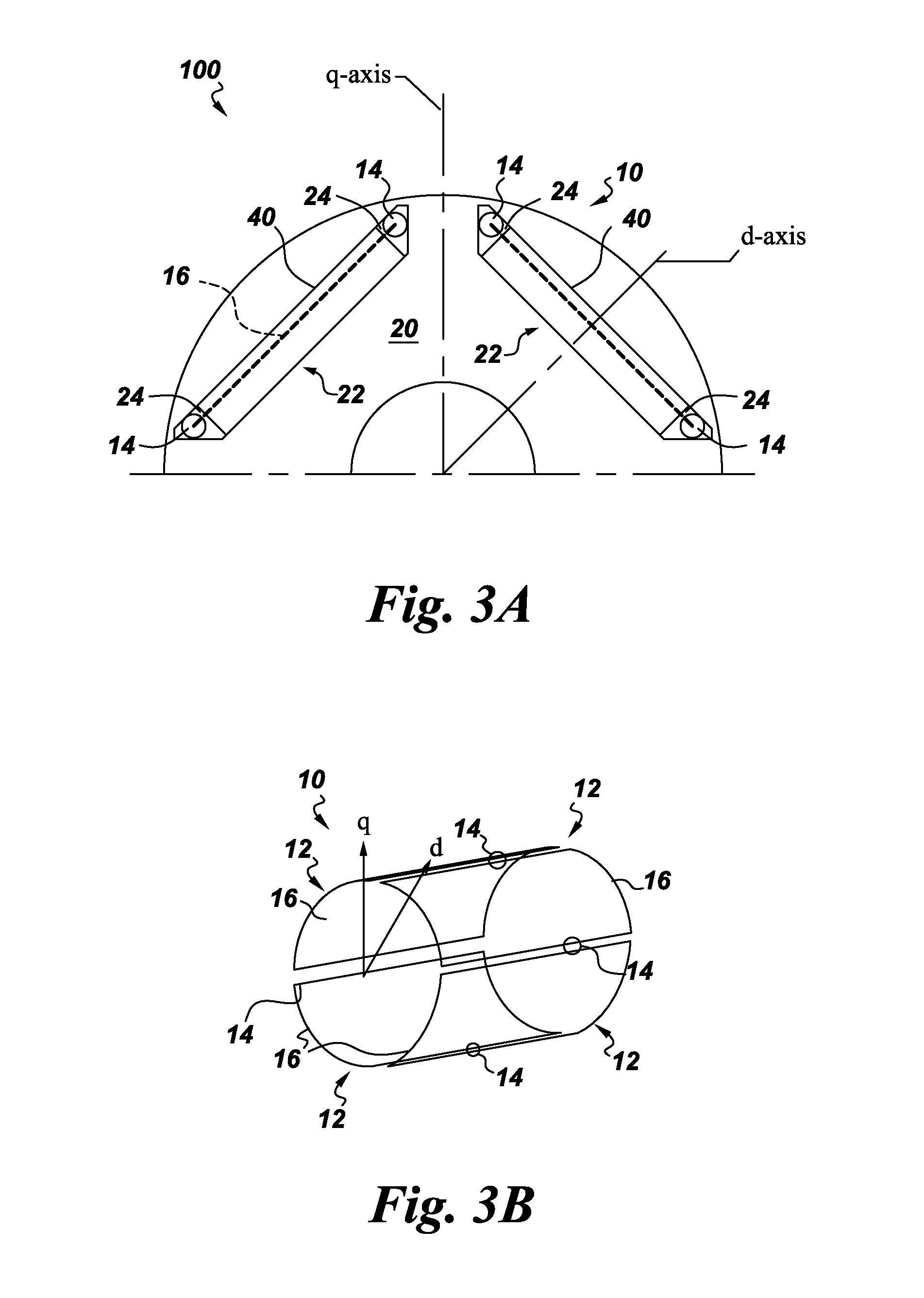
The present invention is about improving electric machines to make them more efficient in their manufacturing and operation. Specifically, the invention includes the use of D-ring implementation of skewed rotor sections in electric machines, such as motors used in vehicles. The invention also includes components and assemblies that provide for the skewed features of these electric machines. For example, a vehicle like an underground mining vehicle may use compact traction motors that use aspects of the invention. These improvements can lead to more technical effects, such as increased speed, reduced size, and higher efficiency of electric machines.

Problems solved by technology

IPM machines unfortunately suffer from both a manufacturing and a technical (i.e., electro-mechanical) shortcoming.
Due to small clearances between the magnets and the slots in the laminations, and the unevenness of such slots along the entire length, the magnets and / or laminations may be damaged during this insertion process.
Further, depending on their magnitude, torque “ripple”, or torque oscillations, of the IPM or with Synchronous Reluctance machines, may result in damage to the rotor, the gearbox, and / or the mechanical system(s) connected to the electric machines (due to fatigue or excessive torque).
Additionally, the frequency of the torque ripple might excite resonant modes of the mechanical system(s), further posing an additional threat to the electric machines and / or surrounding systems.
This methodology suffers from an undesirable increase in manufacturing cost and complexity.
For example, this can cause an additional complexity with the inserting of coils into the slots.
While this method has proven effective in helping reduce torque ripple, it suffers from the undesirable tradeoff of increasing core losses, which, in turn, may harm efficiency.
However, the position sensor (e.g., encoder) along with its cabling and interface electronics contributes a significant portion of the motor drive system cost and overall complexity and is often a major reliability concern.
Since the advent of the high frequency injection method for zero frequency encoderless control, encoderless controls have seen great improvements but none have found success in recovering the full, or near full, torque capability of the machine.
This is due to loss of small signal saliency at high-load levels for the machine.

Method used


Image

  • D-ring implementation in skewed rotor assembly
  • D-ring implementation in skewed rotor assembly
  • D-ring implementation in skewed rotor assembly

Examples


Embodiment Construction

[0069]Unless defined otherwise, technical and scientific terms used herein have the same meaning as is commonly understood by one of ordinary skill in the art with respect to the presently disclosed subject matter. The terms “first”, “second”, and the like, as used herein do not denote any order, quantity, or importance, but rather are used to distinguish one element from another. The terms “a”, “an”, and “the” do not denote a limitation of quantity, but rather denote the presence of at least one of the referenced item, and the terms “front”, “back”, “bottom”, and / or “top”, unless otherwise noted, are used for convenience of description only, and are not limited to any one position or spatial orientation.

[0070]If ranges are disclosed, the endpoints of all ranges directed to the same component or property are inclusive and independently combinable (e.g., ranges of “up to about 25 wt. %,” is inclusive of the endpoints and all intermediate values of the ranges of “about 5 wt. % to abou...


PUM

PropertyMeasurementUnit
Lengthaaaaaaaaaa
Electrical conductoraaaaaaaaaa
Magnetismaaaaaaaaaa

Abstract

An assembly includes multiple adjoined rotor sections each having multiple poles and multiple void rows therethrough that are radially distributed in each of the poles. The rotor sections are skewed in a circumferential direction. The assembly also has multiple conductive rings that substantially surround one of the void rows. A method of assembly and electric machines and vehicles using the assembly are also disclosed. Aspects reduce torque ripple in electric machines and allow for encoderless / sensorless operation in an electric machine using the rotor assembly. The present invention has been described in terms of specific embodiment(s), and it is recognized that equivalents, alternatives, and modifications, aside from those expressly stated, are possible and within the scope of the appending claims.

Description

CROSS REFERENCE TO RELATED APPLICATIONS[0001]This Continuation-In-Part (C.I.P.) application claims the benefit of the Sep. 6, 2013 filing date of U.S. application Ser. No. 14 / 019,630 (Entitled: ELECTRIC MACHINE HAVING OFFSET ROTOR SECTIONS, as amended, attorney docket no. 267026-1). This C.I.P. application also claims the benefit of the Nov. 1, 2012 filing date of U.S. application Ser. No. 13 / 666,283 (Entitled: SENSORLESS ELECTRIC MACHINE, attorney docket no. 264564-1). Both of the aforementioned applications are incorporated herein by reference in their entirety.BACKGROUND OF THE INVENTION[0002]The present invention relates generally to electric machines and, more particularly, to implementations for sensorless electric machines that have skewed rotor sections.[0003]One general application for electric machines, and interior permanent magnet (IPM) machines, in particular, is for use in underground mining vehicles, wherein typically electric wheel motors (e.g., IPM) are connected to...

Claims


Application Information

Patent Timeline
IPC IPC(8): H02K3/16H02K1/27H02K15/03H02K1/24
CPCH02K3/16H02K1/24H02K1/274H02K15/03H02K29/03H02K29/12H02K1/223H02K1/246H02K1/28H02K3/20H02K2201/06Y10T29/49012
Inventor FISENI, ALEXANDER FELIXHUH, KUM-KANGOSAMA, MOHAMEDPAPINI, FRANCESCO
Owner WESTINGHOUSE AIR BRAKE TECH CORP
Learn More