Power converter and method for controlling the same

a power converter and voltage regulation technology, applied in the field of power converters, can solve the problems of complex circuitry design of power converters, difficult to ensure high conversion efficiency with a wide range of switching frequency, and inability to achieve voltage regulation for a wider range of input voltage inputted into the power converters

Active Publication Date: 2014-05-01
DELTA ELECTRONICS INC
View PDF3 Cites 29 Cited by
  • Summary
  • Abstract
  • Description
  • Claims
  • Application Information

AI Technical Summary

Benefits of technology

[0010]Still another aspect of the present disclosure is related to a power converter including a full-bridge converter circuit and a regulation circuit. The full-bridge converter circuit includes a full-bridge circuit having a first and a second input terminals and a first and a second output terminals. The regulation circuit is bridged across the first and the second input terminals of the full-bridge circuit and connected to the first output terminal of the full-bridge circuit. The regulation circuit is configured for operatively regulating an output voltage across the first and the second output terminals of the full-bridge circuit by cooperating with the full-bridge converter circuit, such that the output voltage across the first and the second output terminals of the full-bridge circuit has more than three voltage levels.

Problems solved by technology

However, with LLC converter, under the condition that the power converter is operated with frequency modulation, a wide range of switching frequency is necessary when voltage regulation for a wide range of input voltage inputted into the power converter is required, and this results in complex and difficult circuitry design in the power converter.
High conversion efficiency is also hard to be guaranteed with a wide range of switching frequency.
In other words, the voltage regulation for a wider range of input voltage inputted into the power converter cannot be achieved if the range of switching frequency is not further extended.

Method used


Image

  • Power converter and method for controlling the same
  • Power converter and method for controlling the same
  • Power converter and method for controlling the same

Examples


first embodiment

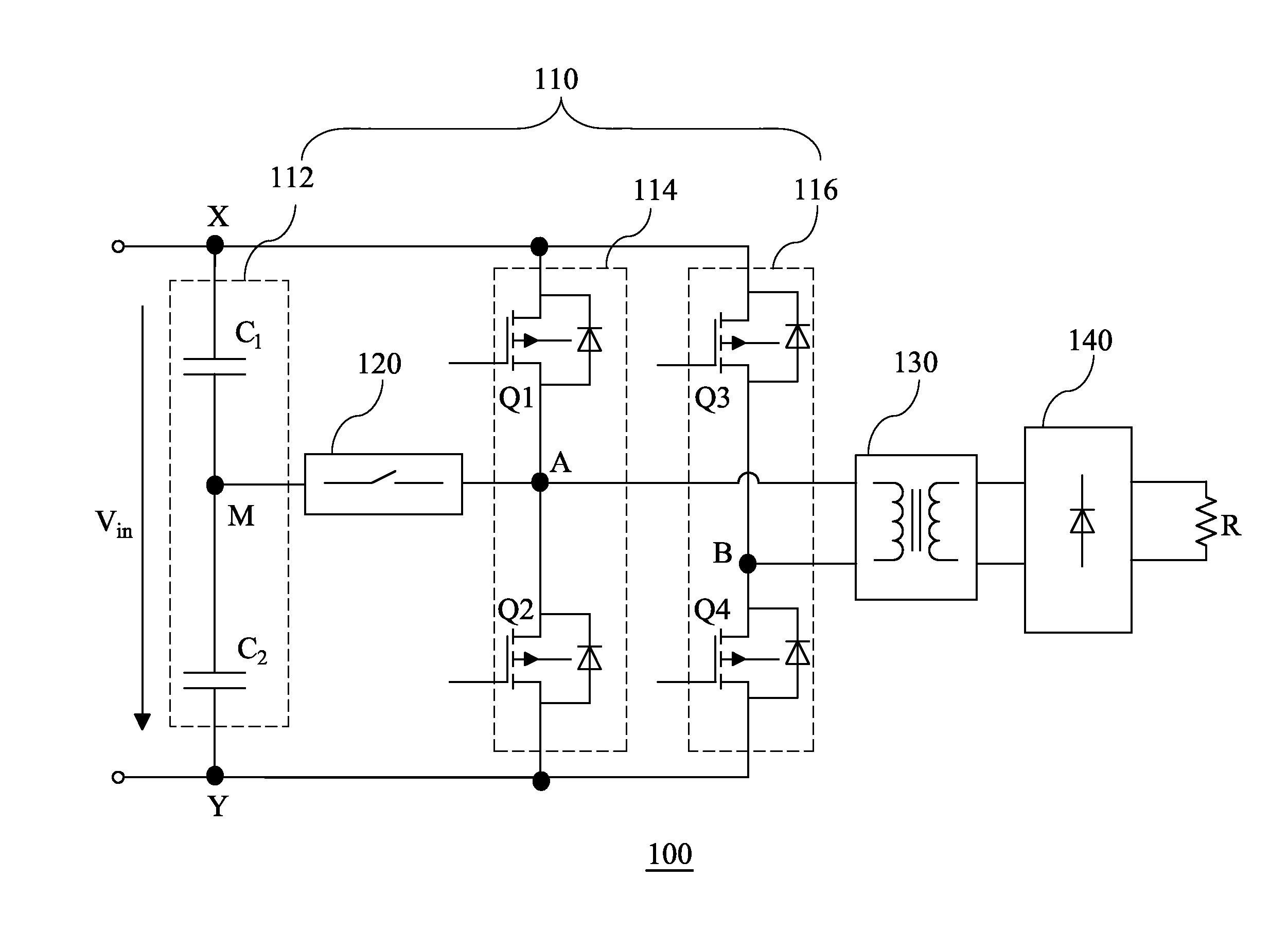
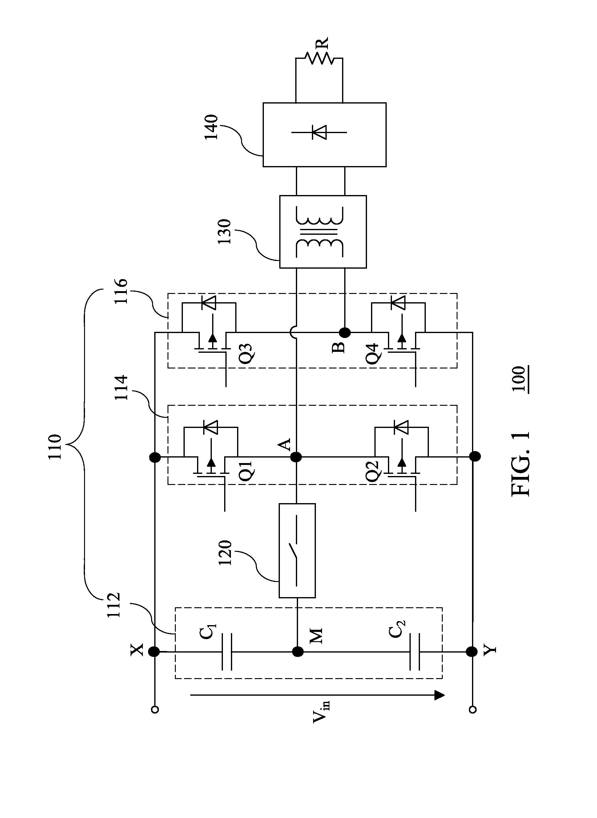
[0029]FIG. 1 is a schematic diagram of a power converter according to the present disclosure. As shown in FIG. 1, the power converter 100 includes a bridge circuit (e.g., a full-bridge inverter) 110, a switch module 120, an isolation stage 130 and an output stage 140. The bridge circuit 110 has a first input terminal X and a second input terminal Y both configured for receiving an input voltage Vin, and a first output terminal A and a second output terminal B both configured for generating an output voltage VAB therebetween. The bridge circuit 110 further includes bridge arms 112, 114, and 116. The bridge arm 112 includes two capacitor units C1 and C2 connected in series at a middle point M between the first input terminal X and the second input terminal Y of the bridge circuit 110. The bridge arm 114 includes switch devices Q1 and Q2 connected in series at the first output terminal A between the first input terminal X and the second input terminal Y of the bridge circuit 110. The b...

second embodiment

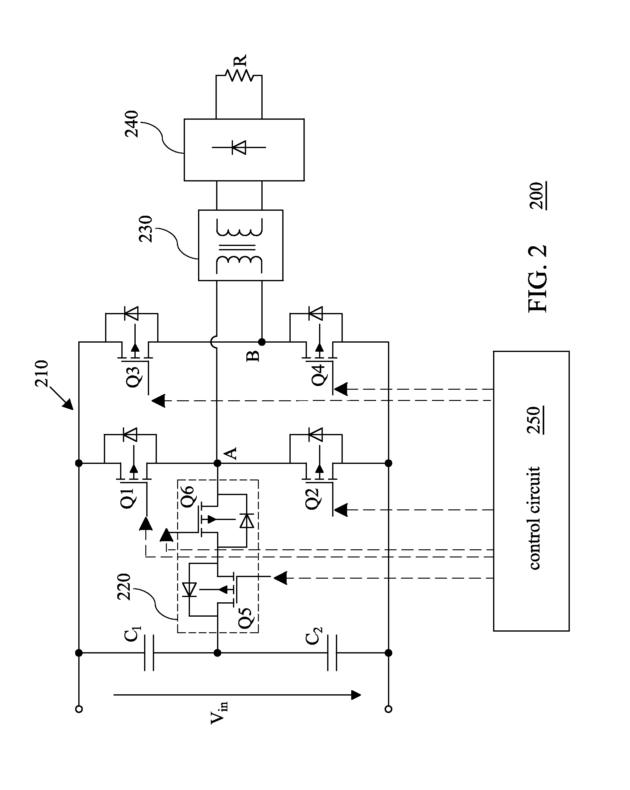
[0033]FIG. 2 is a schematic diagram of a power converter according to the present disclosure. As shown in FIG. 2, the power converter 200 includes circuits that are similar to those shown in FIG. 1, and thus the circuits are not further detailed herein. Compared to the embodiment shown in FIG. 1, the switch module 220 in the power converter 200 further includes switch devices Q5 and Q6, and the switch devices Q5 and Q6 are connected anti-serially between the middle point M and the first output terminal A of the bridge circuit 210.

[0034]Moreover, the power converter 200 may further include a control circuit 250 for controlling the switch devices Q1-Q6, in which the switch devices Q1 and Q6 are switched on complementarily, the switch devices Q2 and Q5 are switched on complementarily, and the switch devices Q3 and Q4 are switched on complementarily. Notably, each of the aforementioned embodiments and following embodiments may further include a control circuit that is similar to or the ...

third embodiment

[0036]FIG. 3 is a schematic diagram of a power converter according to the present disclosure. As shown in FIG. 3, the power converter 300 includes circuits that are similar to those shown in FIG. 2, and thus the circuits are not further detailed herein. Compared to the embodiment shown in FIG. 2, the isolation stage 330 can further include a transformer Tr having a primary winding circuit connected between the first output terminal A and the second output terminal B of the bridge circuit 310, and a secondary winding circuit connected to the input terminals of the output stage 340, as illustrated in FIG. 3.


PUM


Abstract

A power converter includes a full-bridge converter circuit and a regulation circuit. The full-bridge converter circuit includes a full-bridge circuit having a first and a second input terminals and a first and a second output terminals. The regulation circuit is bridged across the first and the second input terminals of the full-bridge circuit and connected to the first output terminal of the full-bridge circuit. The regulation circuit is configured for operatively regulating an output voltage across the first and the second output terminals of the full-bridge circuit by cooperating with the full-bridge converter circuit, such that the output voltage across the first and the second output terminals of the full-bridge circuit has more than three voltage levels. A method for controlling a power converter is also disclosed herein.

Description

RELATED APPLICATIONS[0001]This application claims priority to Chinese Application Serial Number 201210421131.8, filed Oct. 29, 2012, which is herein incorporated by reference.BACKGROUND[0002]1. Technical Field[0003]The present disclosure relates to a power converter. More particularly, the present disclosure relates to voltage regulation of a power converter.[0004]2. Description of Related Art[0005]As energy demand increases significantly nowadays, renewable energy generation, such as wind power, fuel cell, solar cells (i.e., photovoltaic cells, PV), etc., becomes more and more attractive. In such application, power conversion with high efficiency, high power density, high reliability and low cost is normally required, particularly for the energy applications with wide range.[0006]Typically, a power converter with high efficiency is provided in the aforementioned power conversion applications and the power converter is usually operated with high switching frequecy under a certain co...

Claims


Application Information

Patent Timeline
Patent Type & Authority Applications(United States)
IPC IPC(8): H02M3/335
CPCH02M3/335H02M1/10H02M3/33573H02M3/01
Inventor ZHU, XUAN-CAIWENG, BING-WEN
Owner DELTA ELECTRONICS INC
Why Eureka
Try Eureka