
Method and system for cooperative congestion detection in cellular networks

Active Publication Date: 2014-05-01
OPANGA NETWORKS
View PDF5 Cites 22 Cited by
  • Summary
  • Abstract
  • Description
  • Claims
  • Application Information

AI Technical Summary

Benefits of technology

The patent text describes a method for detecting congestion in a network system and sharing the information with other users. The method involves sending a file segment to a receiving system, measuring the congestion based on the transfer of the file segment, and communicating the congestion information to the receiving system. This allows for better management of network congestion and improved data transfer between users. The technical effect of this method is to improve network efficiency and reduce delays in data transfer.

Problems solved by technology

Congestion can occur if the demand for a shared channel's bandwidth resources nears or exceeds the channel's capacity.
Under these circumstances, the active users of the shared channel may come into conflict as each user attempts to complete individual data throughputs.
Thus, the periodic measurements taken in accordance to these protocols also present a traffic load to a network.
Accordingly, if many end user terminals attempt to detect congestion in this manner, the aggregate burden to the network traffic exacerbates any congestion that may already be present.
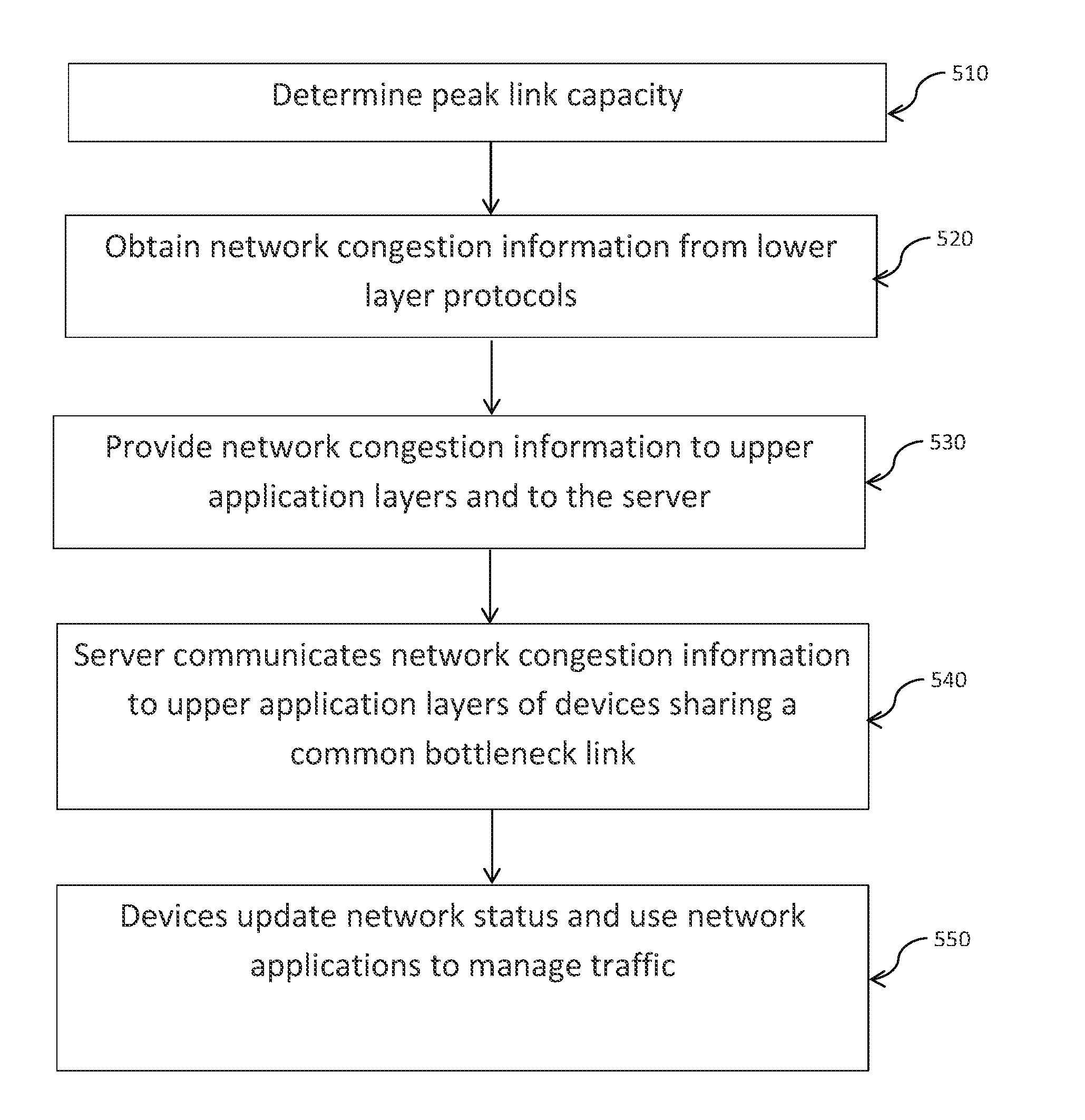
Furthermore, congestion detection and control is often assigned to lower protocol layers such as TCP, while upper application protocol layers and application programming interfaces typically do not have access to the congestion status of the network.
Without access to congestion information upper application layers and application programming have difficulty reacting to or mitigating the congestion.

Method used


Image

  • Method and system for cooperative congestion detection in cellular networks
  • Method and system for cooperative congestion detection in cellular networks
  • Method and system for cooperative congestion detection in cellular networks

Examples


Embodiment Construction

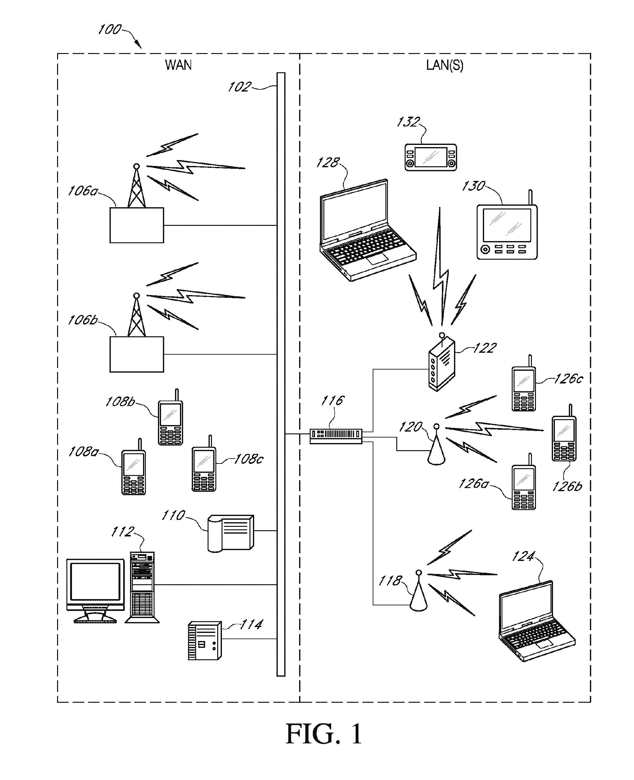
[0029]FIG. 1 illustrates a networked computing system 100 including various wireline and wireless computing devices that may be utilized to implement any of the network traffic and radio communications quality monitoring or data content transfer optimization processes associated with various embodiments of the present invention. The specific network configuration shown in FIG. 1 is intended to provide an example of a high-level computing system capable of facilitating various network communications processes of embodiments disclosed herein. Network configuration and topology changes could be made to the networked computing system 100 of FIG. 1, without departing from the spirit and scope of the present disclosure.

[0030]In an embodiment, the networked computing system 100 includes a group of service provider devices; a data communications network 102; a variety of remote user equipment; one or more devices to facilitate data communications; and one or more local user equipment. In ad...


PUM


Abstract

Congestion information is determined based on a file segment transferred to one of user terminals. The congestion information is available to a server or controller communicatively linked with a plurality of user terminals. The congestion information is shared with other user terminals that share a bottleneck link.

Description

CROSS REFERENCE TO RELATED APPLICATIONS[0001]This application claims the benefit of U.S. Provisional Patent Application No. 61 / 718,526, filed on Oct. 25, 2012, which is incorporated herein by reference.BACKGROUND[0002]Embodiments relate to the field of computer networks and communications over computer networks, including communications over wireless networks.[0003]Many computer networks in existence today communicate through the transfer of data. Some examples include networks that can function independently (e.g., as Local Area Networks or LANs) or collectively as part of a group of interconnected networks (e.g., Wide Area Networks or WANs), such as the World Wide Web. Some of these networks include technologies that facilitate relatively fast, high data-rate transmissions (e.g., wired, fiber-optic, cable, and Digital Subscriber Line networks). Others facilitate slower data-rate transmissions (e.g., 3G cellular networks).[0004]Mobile broadband services are becoming very popular in...

Claims


Application Information

Patent Timeline
IPC IPC(8): H04L12/70
CPCH04L47/10H04W28/0284H04L47/11H04L12/28
Inventor HARRANG, JEFFREY P.GIBBONS, DAVIDBURNETTE, JOHN M.
Owner OPANGA NETWORKS
Learn More