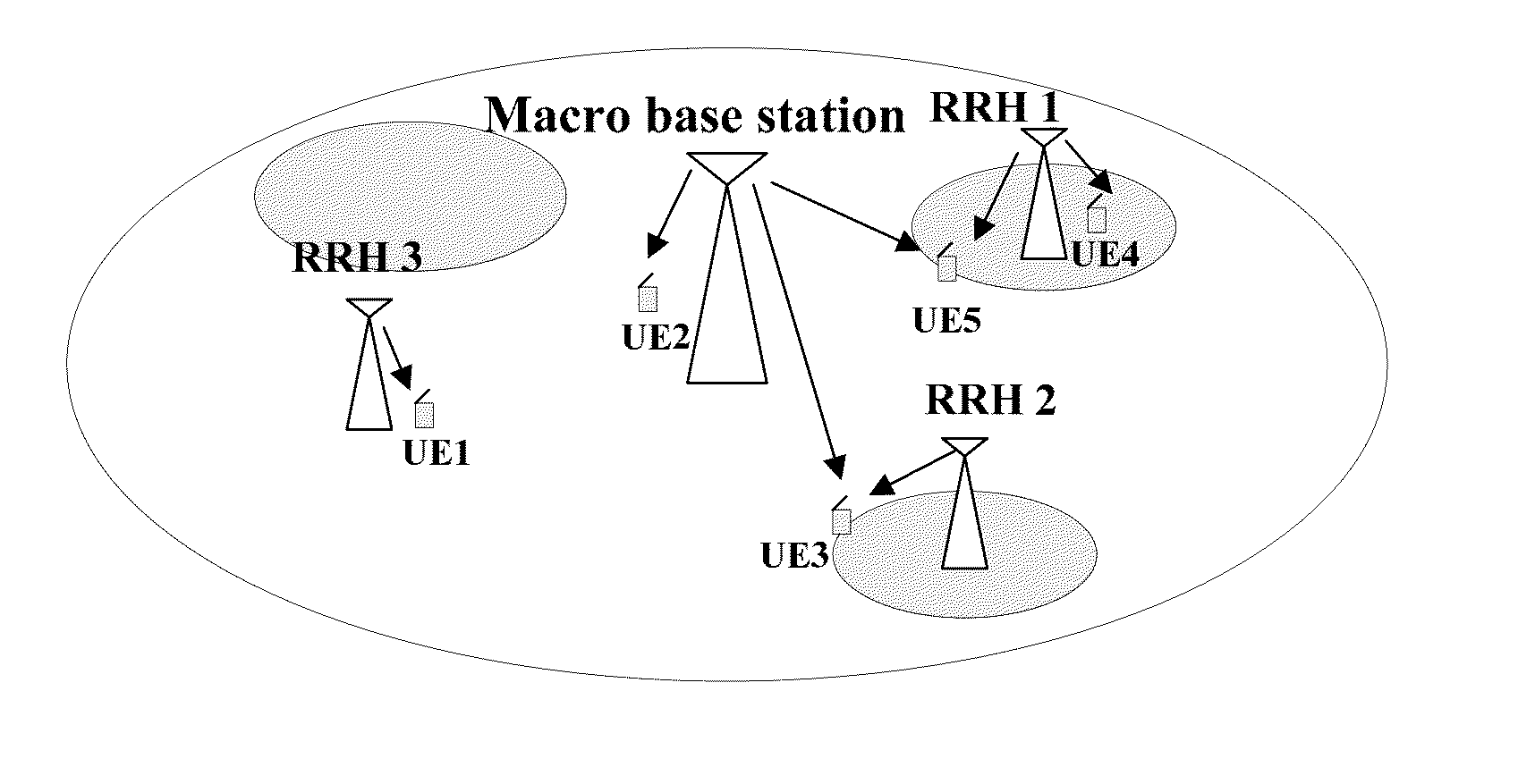
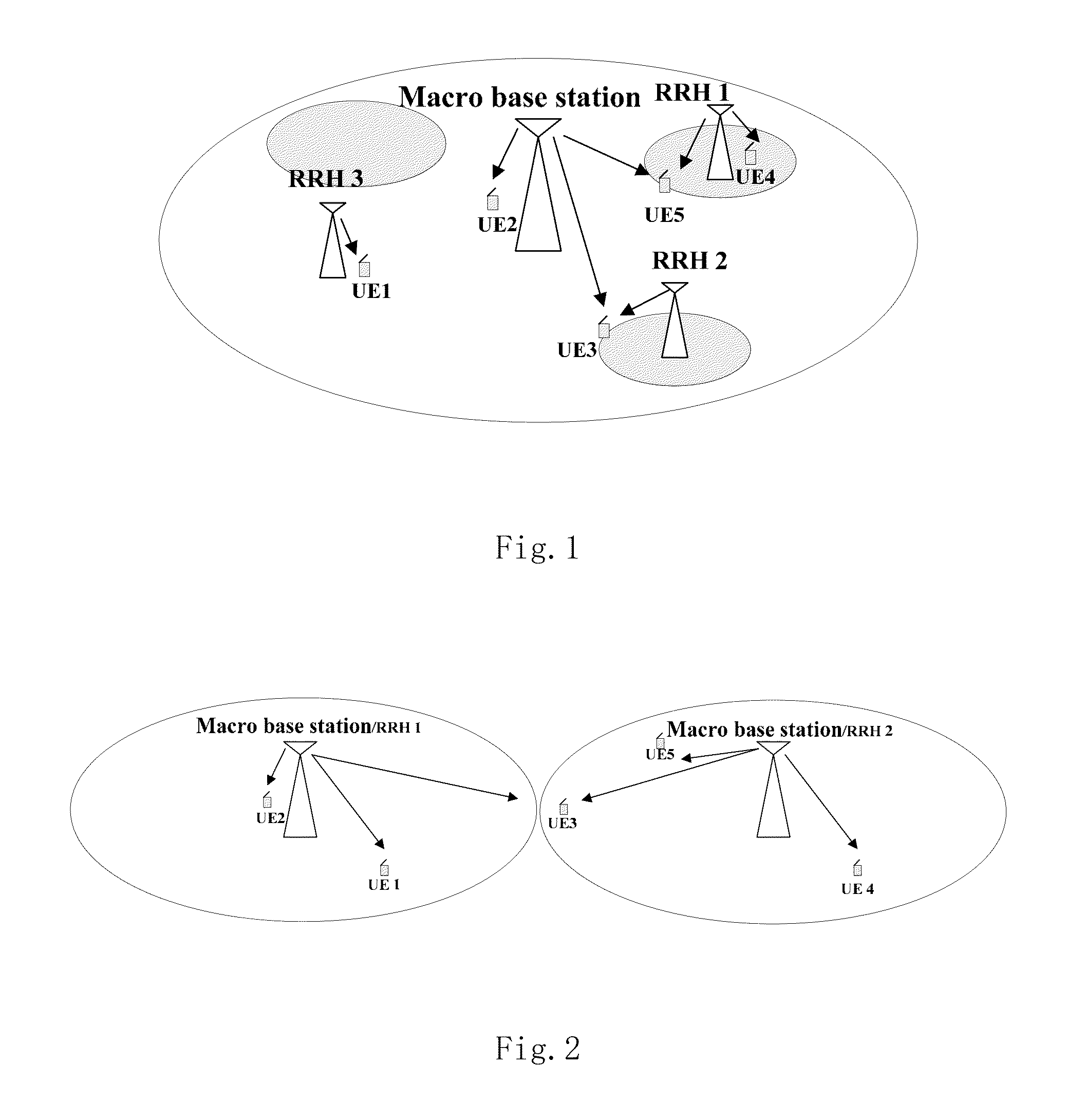
Sounding reference symbol sending method, base station, and user equipment
a reference symbol and sounding technology, applied in the field of wireless communication, can solve the problems of ineffective solution of the above problem, the inability to use srs resources, and the inability to achieve the effect of reducing the cost of srs resources
- Summary
- Abstract
- Description
- Claims
- Application Information
AI Technical Summary
Benefits of technology
Problems solved by technology
Method used
Image
Examples
embodiment 1
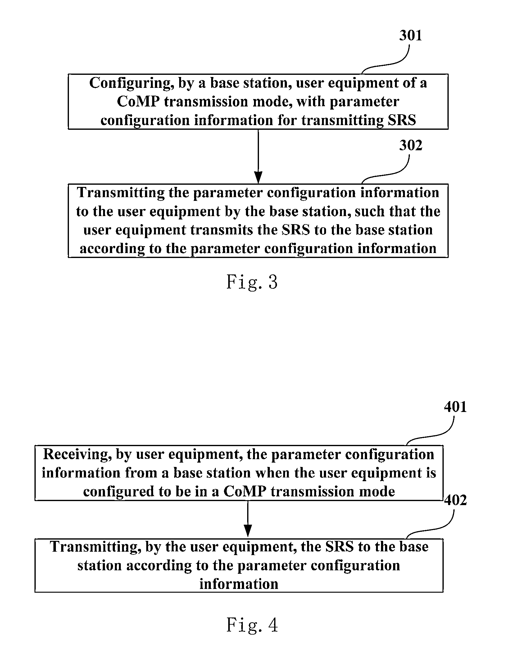
[0042]FIG. 3 is a flowchart of the method for transmitting SRS of Embodiment 1 of the present invention. As shown in FIG. 3, at a base station side, the method includes:
[0043]step 301: configuring, by a base station, user equipment of a CoMP transmission mode, with parameter configuration information for transmitting SRS, the parameter configuration information including a frequency comb of the SRS and one or more pieces of the following information: cyclic shift, root sequence information, power control information, and transmission duration information, of the SRS; and
[0044]step 302: transmitting, by the base station, the parameter configuration information to the user equipment, such that the user equipment transmits the SRS to the base station according to the parameter configuration information.
[0045]In this embodiment, for the CoMP transmission mode, a parameter value of said parameter configuration information is different from a parameter value of an SRS in a non-CoMP transm...
embodiment 2
[0048]FIG. 4 is a flowchart of the method for transmitting SRS of Embodiment 2 of the present invention. As shown in FIG. 4, at user equipment side, the method includes:
[0049]step 401: receiving, by user equipment, parameter configuration information transmitted by a base station, when the user equipment is configured to be in a CoMP transmission mode, the parameter configuration information including a frequency comb of the SRS and one or more pieces of the following information: cyclic shift, root sequence information, power control information, and transmission duration information, of the SRS;
[0050]In this embodiment, the user equipment may be explicitly or impliedly configured to be in the CoMP transmission mode; for example, the user equipment is notified by high-layer signaling to enter the CoMP transmission mode, that is, a new transmission mode is defined for the CoMP; or the user equipment is impliedly entered into the CoMP transmission mode by configuring the user equipme...
embodiment 3
[0055]FIG. 5 is a flowchart of the method for transmitting SRS of Embodiment 3 of the present invention. As shown in FIG. 5, at a base station side, the method includes:
[0056]step 501: configuring, by a base station, user equipment of a CoMP transmission mode, with parameter configuration information for transmitting SRS;
[0057]In this embodiment, for example, the parameter configuration information includes cyclic information of the SRS, bandwidth information of the SRS, a frequency comb of the SRS, cyclic shift of the SRS, root sequence information of the SRS, power control information of the SRS, and transmission duration information of the SRS;
[0058]What described above is an embodiment of the present invention only, and one or more pieces of the above parameter configuration information may be configured as actually required;
[0059]step 502: generating, by the base station, DCI indicative of SRS resource allocation, the DCI containing indication information corresponding to the p...
PUM
 Abstract
Description
Claims
Application Information
 - R&D
- Intellectual Property
- Life Sciences
- Materials
- Tech Scout
- Unparalleled Data Quality
- Higher Quality Content
- 60% Fewer Hallucinations
Browse by: Latest US Patents, China's latest patents, Technical Efficacy Thesaurus, Application Domain, Technology Topic, Popular Technical Reports.
© 2025 PatSnap. All rights reserved.Legal|Privacy policy|Modern Slavery Act Transparency Statement|Sitemap|About US| Contact US: help@patsnap.com


