

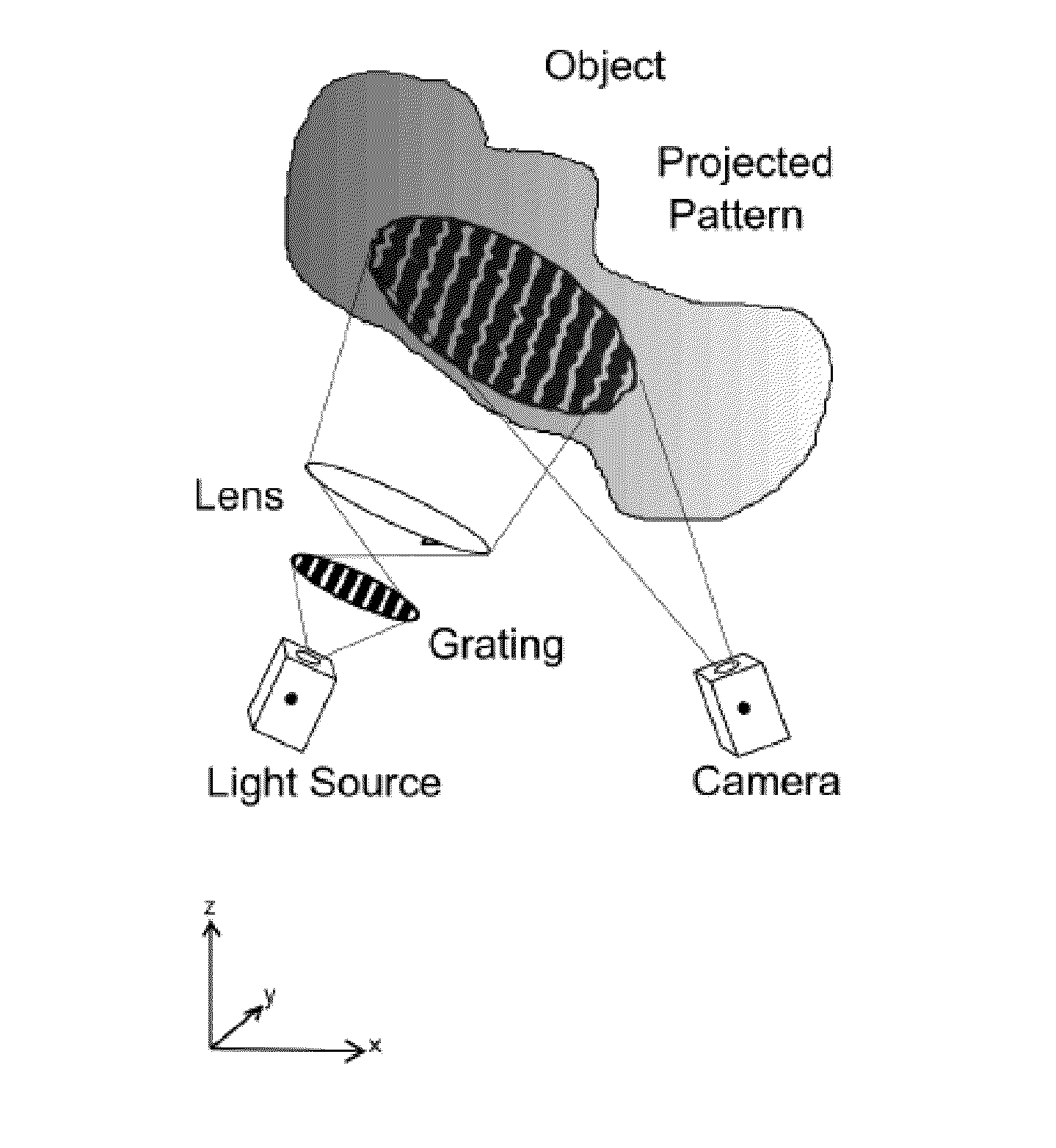
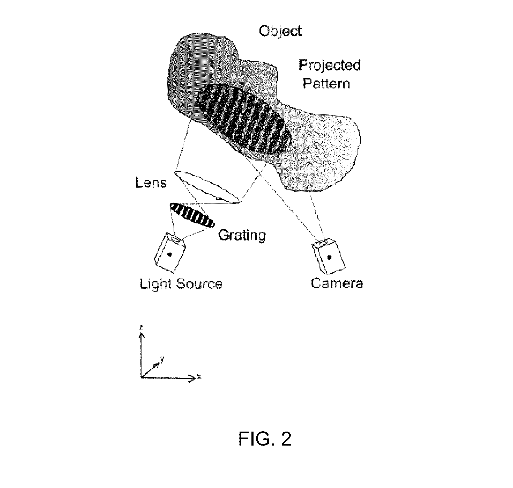
3D mapping using structured light and formation of custom surface contours
a technology of structured light and surface contours, applied in the direction of instruments, transportation and packaging, chemistry apparatuses and processes, etc., can solve the problems of not having sufficient imaging sensitivity for static 3d contour mapping purposes, the 3d scanning technique has not been widely used to produce items having a surface contour personalized for an individual, and the time-consuming and costly casting techniques
- Summary
- Abstract
- Description
- Claims
- Application Information
AI Technical Summary
Benefits of technology
Problems solved by technology
Method used
Image

Examples
Embodiment Construction
[0029]Definitions and Overview
[0030]Before describing the present invention in detail, it is to be understood that the invention is not limited to any specific manufacturers of portable devices as such may vary. It is also to be understood that the terminology used herein is for the purpose of describing particular embodiments only, and is not intended to be limiting.
[0031]In addition, as used in this specification and the appended claims, the singular article forms “a,”“an,” and “the” include both singular and plural referents unless the context clearly dictates otherwise. Thus, for example, reference to “a light source” includes a single light source as well as an assembly of light sources, reference to “a camera” includes a plurality of cameras as well as a single camera, and the like.
[0032]In this specification and in the claims that follow, reference will be made to a number of terms that shall be defined to have the following meanings, unless the context in which they are empl...
PUM
| Property | Measurement | Unit |
|---|---|---|
| distance | aaaaa | aaaaa |
| angle | aaaaa | aaaaa |
| volume | aaaaa | aaaaa |
Abstract
Description
Claims
Application Information