
Impact resistant material

a technology of impact resistance and material, applied in the field of composite materials, can solve the problems of limited hardness and ductility of the armor

Inactive Publication Date: 2014-05-01
SDC MATERIALS
View PDF5 Cites 39 Cited by
  • Summary
  • Abstract
  • Description
  • Claims
  • Application Information

AI Technical Summary

Problems solved by technology

However, the resulting armor is limited in both its hardness and its ductility.

Method used

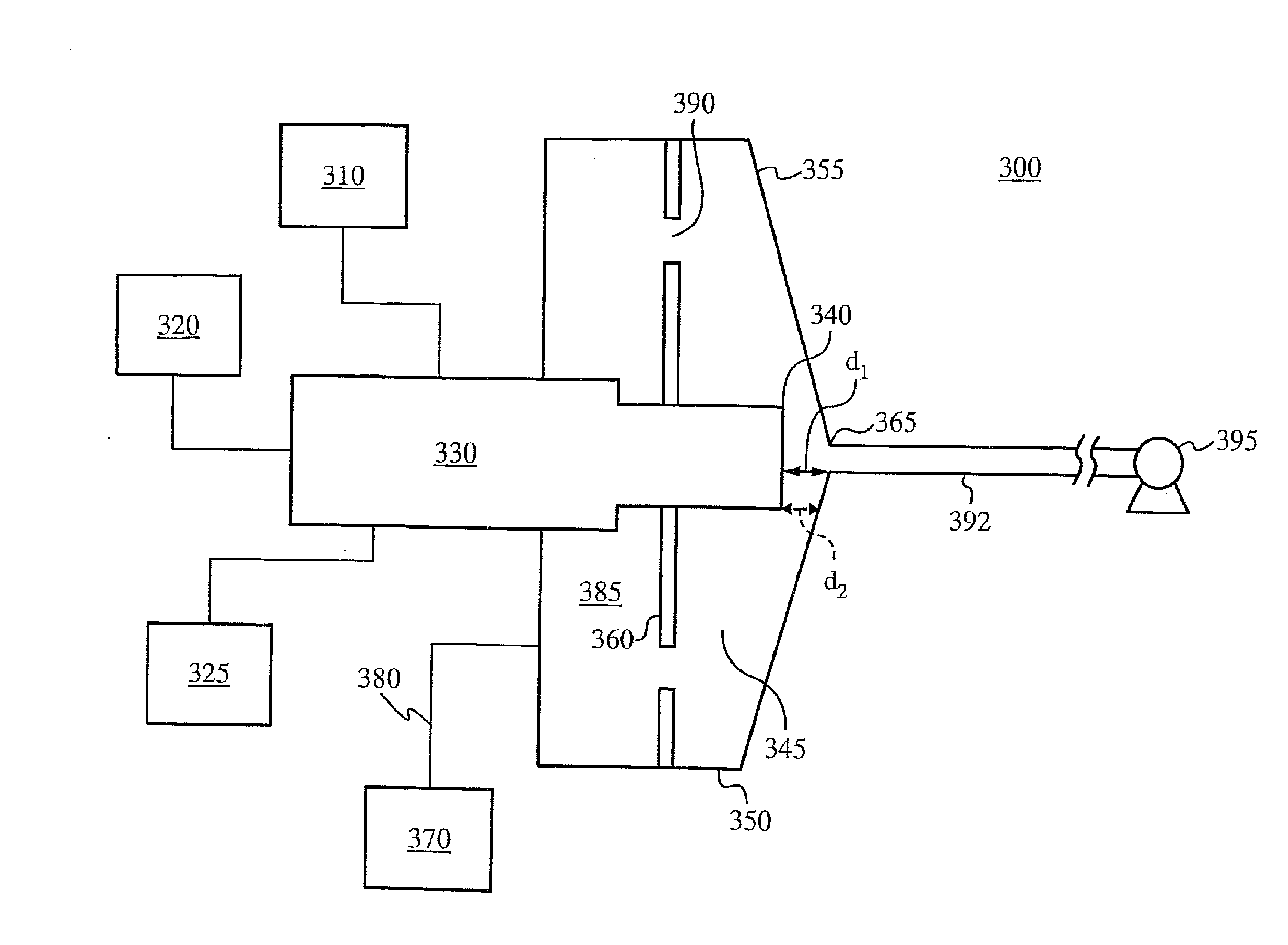
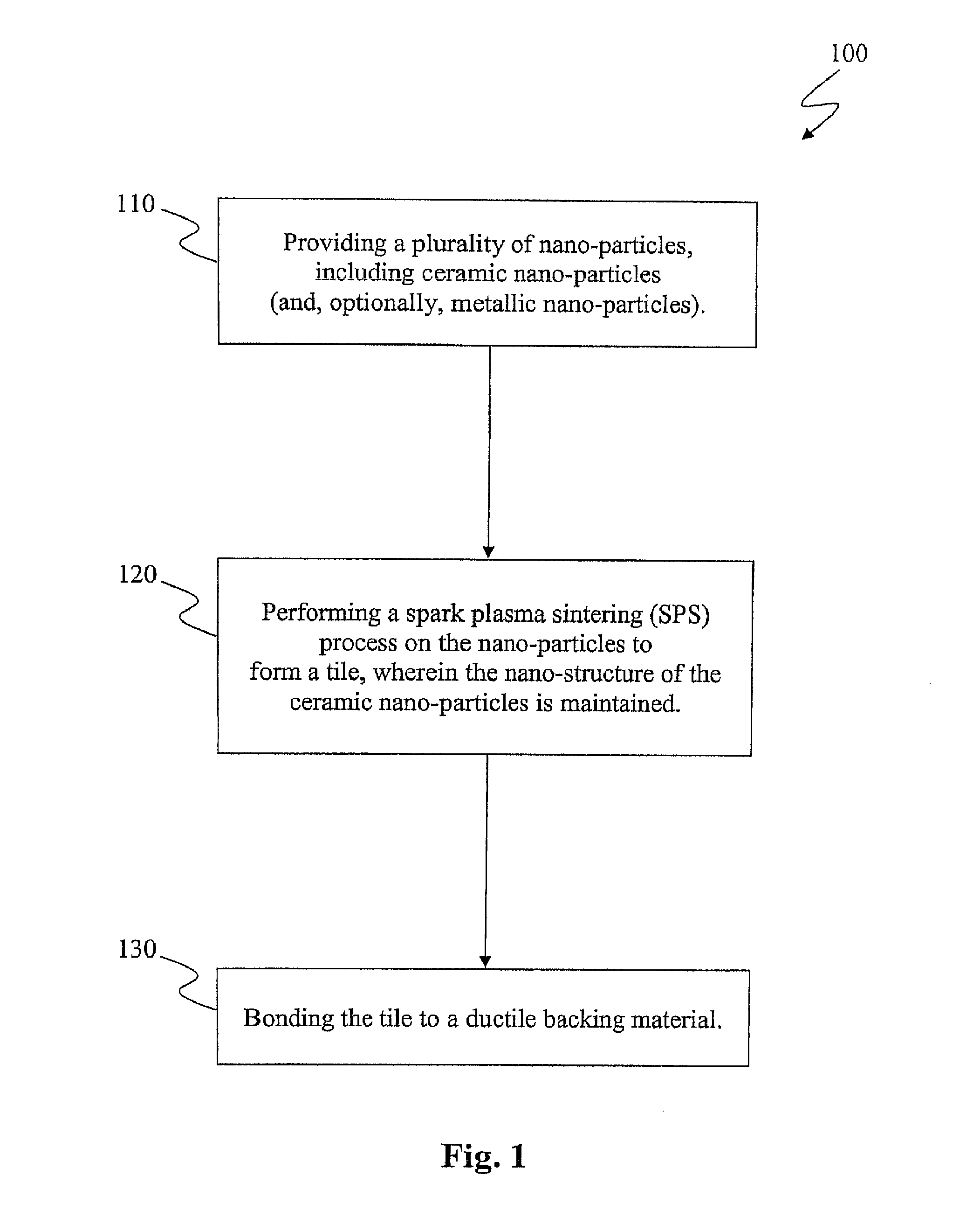
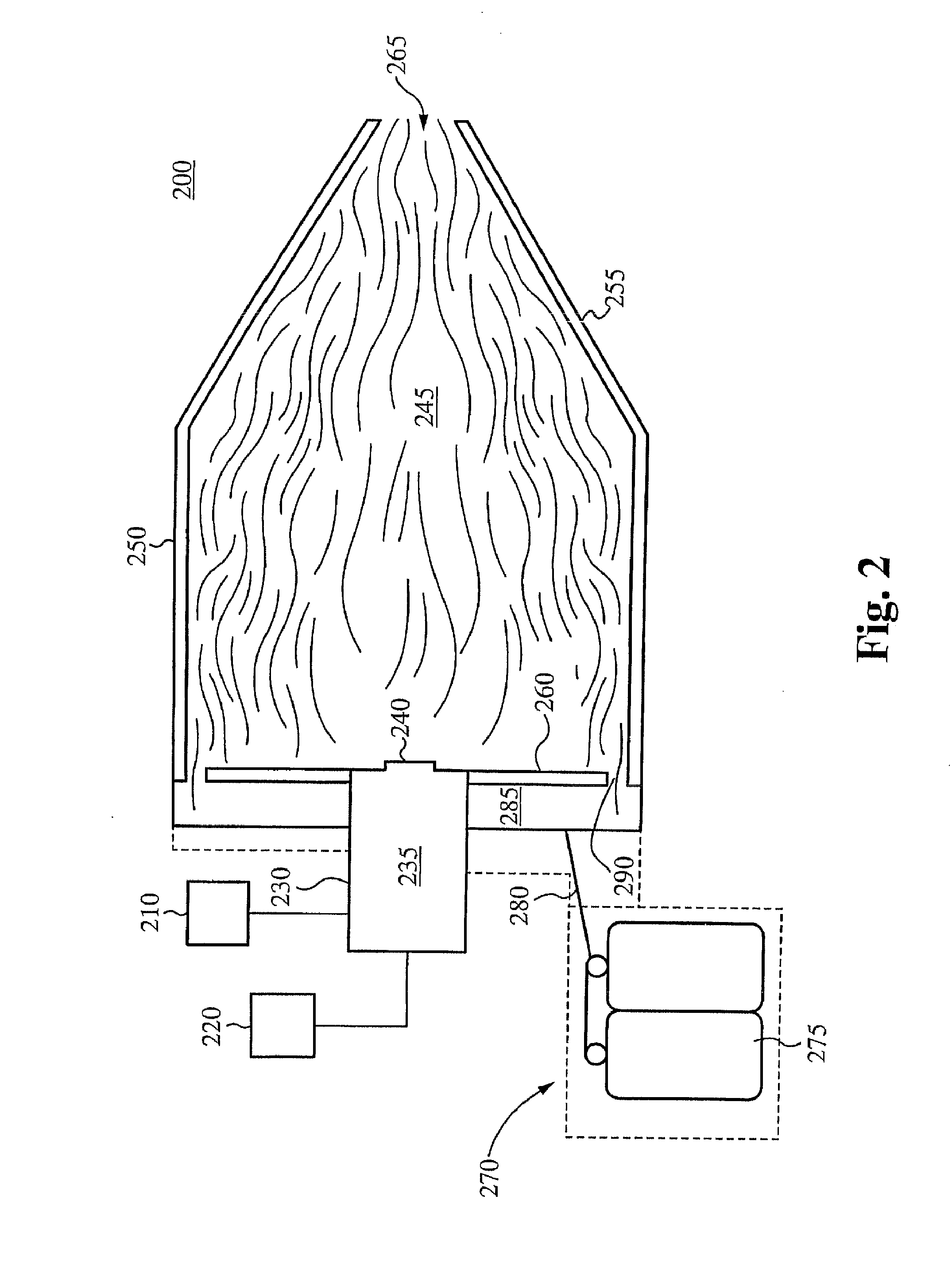

Image

  • Impact resistant material
  • Impact resistant material
  • Impact resistant material

Examples


Embodiment Construction

[0032]The following description is presented to enable one of ordinary skill in the art to make and use the invention and is provided in the context of a patent application and its requirements. Various modifications to the described embodiments will be readily apparent to those skilled in the art and the generic principles herein may be applied to other embodiments. Thus, the present invention is not intended to be limited to the embodiment shown but is to be accorded the widest scope consistent with the principles and features described herein.

[0033]This disclosure refers to both particles and powders. These two terms are equivalent, except for the caveat that a singular “powder” refers to a collection of particles. The present invention may apply to a wide variety of powders and particles. Powders that fall within the scope of the present invention may include, but are not limited to, any of the following: (a) nano-structured powders (nano-powders), having an average grain size l...


PUM

PropertyMeasurementUnit
grain sizeaaaaaaaaaa
Reynolds Numberaaaaaaaaaa
grain sizeaaaaaaaaaa

Abstract

A method of making a tile, the method comprising: providing a plurality of nano-particles, wherein the plurality of nano-particles comprises a plurality of ceramic nano-particles; and performing a spark plasma sintering (SPS) process on the plurality of nano-particles, thereby forming a tile comprising the plurality of nano-particles, wherein the nano-structure of the nano-particles is present in the formed tile. In some embodiments, the tile is bonded to a ductile backing material.

Description

CROSS-REFERENCE TO RELATED APPLICATIONS[0001]This application claims priority to U.S. Provisional Patent Application Ser. No. 61 / 284,329, filed Dec. 15, 2009 and entitled “MATERIALS PROCESSING,” which is hereby incorporated herein by reference in its entirety as if set forth herein.FIELD OF THE INVENTION[0002]The present invention relates to the field of composite materials. More specifically, the present invention relates to the formation of composite materials using a novel ceramic tile.BACKGROUND OF THE INVENTION[0003]While composite materials have a variety of different applications, all of which are within the scope of the present invention, they may be particularly useful in the production of body armor, such as bullet-proof vests.[0004]Currently, body armor is formed by bonding two types of armor together. A meltable plate is bonded to a hard plate via melting in an autoclave. However, the resulting armor is limited in both its hardness and its ductility.SUMMARY OF THE INVENT...

Claims


Application Information

Patent Timeline
Patent Type & Authority Applications(United States)
IPC IPC(8): B28B23/00
CPCB28B23/0087B01J23/42B01J35/0013B01J37/349B82Y30/00B82Y40/00B32B37/12B32B2037/1253B32B2571/02B28B11/243B32B5/16B32B27/14B32B2264/107F41H5/0414C23C4/134B32B7/12B01J23/8926B01J37/00B32B37/14
Inventor BIBERGER, MAXIMILIAN A.
Owner SDC MATERIALS
Learn More