

Memory control apparatus and memory control method
a memory control and memory control technology, applied in the direction of memory adressing/allocation/relocation, instruments, static indicating devices, etc., can solve the problems of unnecessary pre-charge, affecting and requiring delay in issuance of any one of the commands, so as to improve the performance of memory access
- Summary
- Abstract
- Description
- Claims
- Application Information
AI Technical Summary
Benefits of technology
Problems solved by technology
Method used
Image

Examples
first embodiment
[0022]A synchronous DRAM used in this embodiment will be described. The synchronous DRAM includes a number of memory elements arranged in a grid, as shown in FIG. 7, and specifies an access target memory element by a combination of a row address and a column address input from the outside. FIG. 7 shows a state in which memory elements indicated by hatching are specified. Data input and output for the synchronous DRAM are done by causing the memory control apparatus to issue commands to be described below. The commands include:
(A) an ACTIVE command to specify and activate a column address;
(B) a READ command to specify a row address and instruct data output;
(C) a WRITE command to specify a row address and instruct data storage;
(D) a PRE command to perform inactivation (precharge);
(E) a READ A command to specify a row address, output data, and after the data output, automatically perform precharge; and
(F) a WRITE A command to specify a row address, store data, and after the data storag...
second embodiment
[0036]A function of burst termination is implemented in a DRAM to reduce unnecessary memory access to the DRAM when the data amount in one memory transfer is smaller than the burst transfer unit of the DRAM. For example, in a DRAM of DDR2 specifications, the READ command or WRITE command can use the termination function, though burst termination for the READ A command or WRITE A command is prohibited. Hence, although the total number of command issuances can be decreased by using the READ A command or WRITE A command, burst termination is impossible. In this embodiment, using a command with precharge for the READ command or WRITE command that does not need burst termination will be examined.
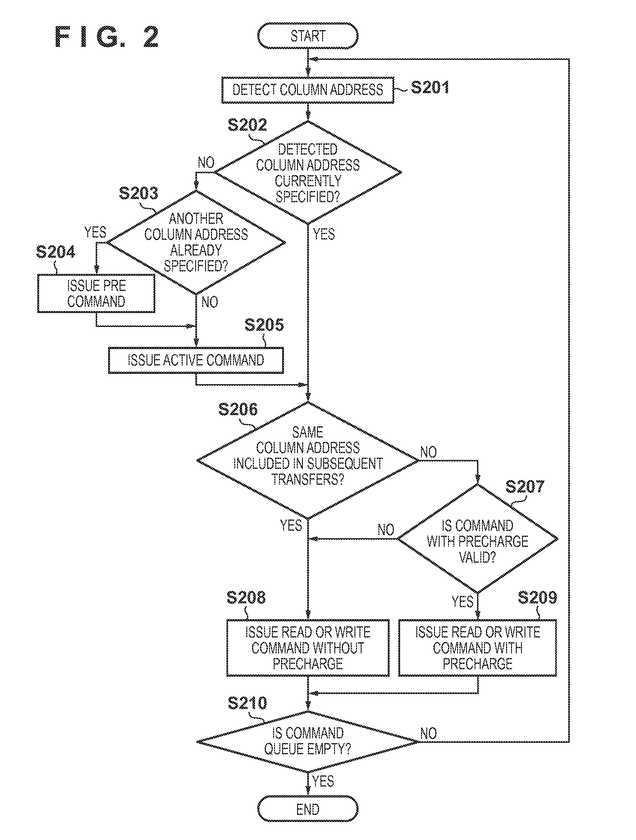
[0037]FIG. 3 is a flowchart showing processing executed by command control units 103 to 106 according to this embodiment. Steps S301 to S305 of FIG. 3 are the same processes as steps S201 to S205 of FIG. 2, respectively. Processing from step S306 is different from the first embodiment. Hence, pro...
third embodiment
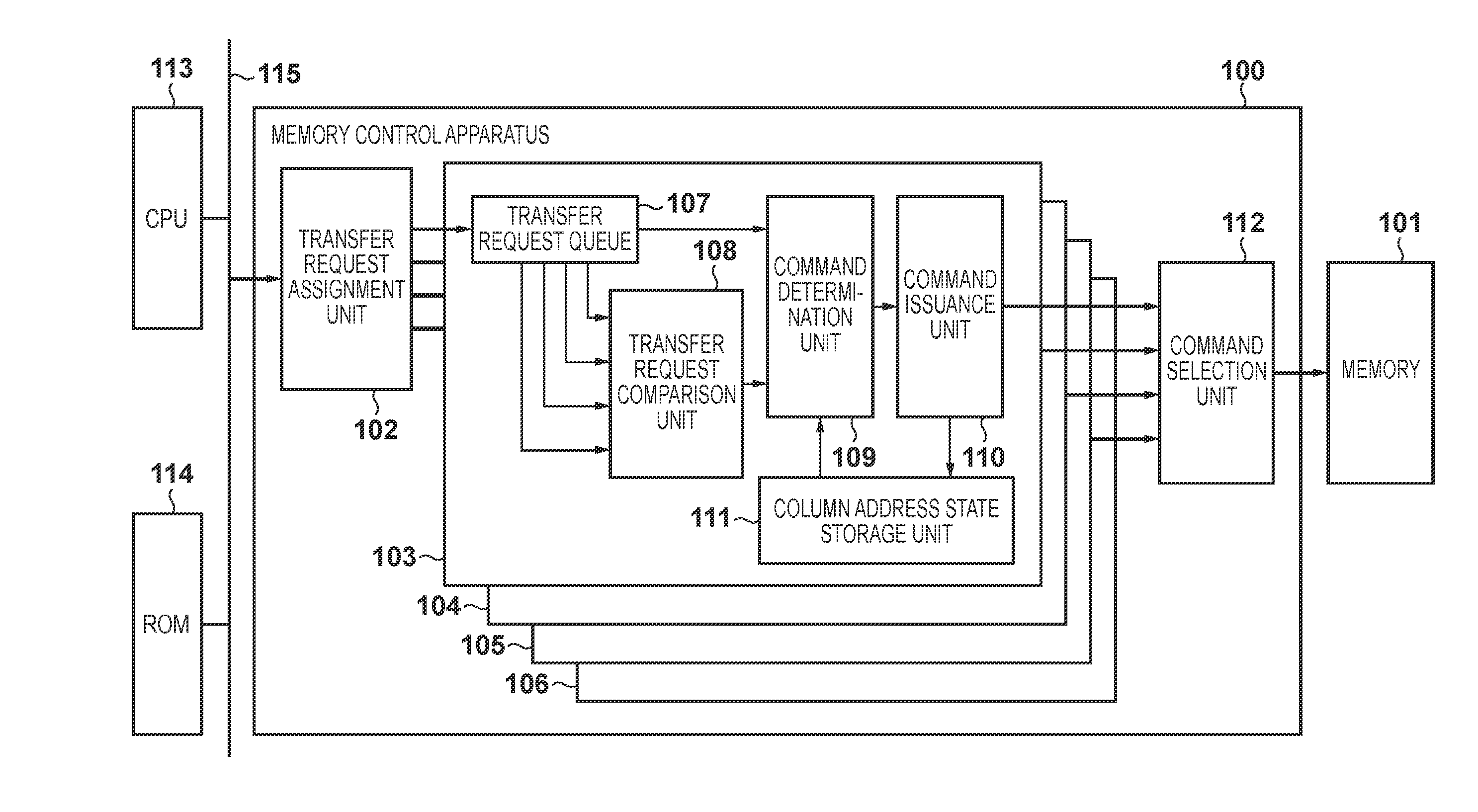
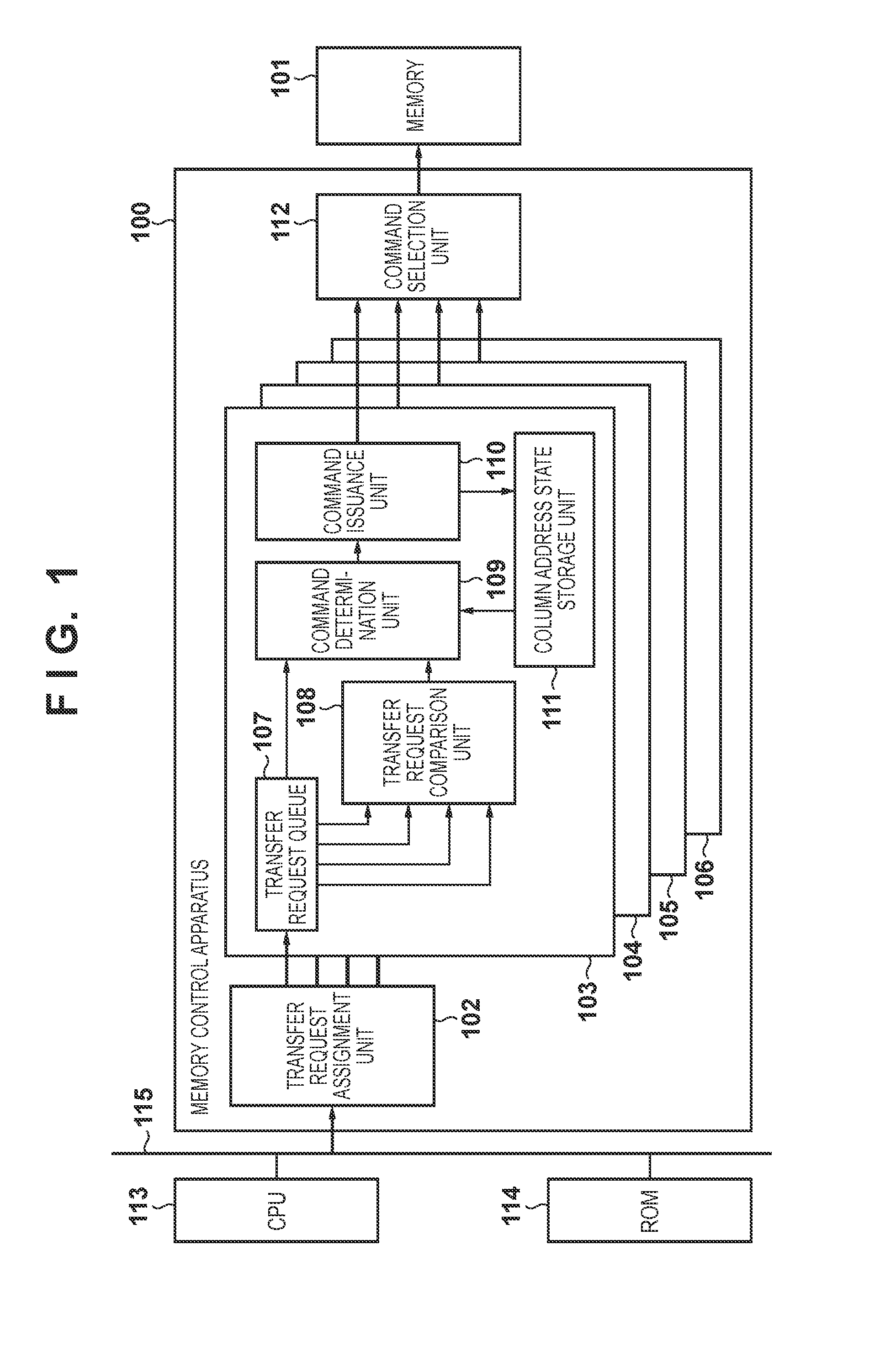
[0040]FIG. 4 is a flowchart showing processing executed by command control units 103 to 106 according to this embodiment. Steps S401 to S405 of FIG. 4 are the same processes as steps S201 to S205 of FIG. 2, respectively. Processing from step S406 is different from the first embodiment. Hence, processing from step S406 will be described. When specifying the column address is completed, a subsequent transfer group stored in a transfer request queue 107 is confirmed (step S406). If the column addresses of the subsequent transfer requests include the same column address as the column address to be accessed next (YES in step S406), memory access is performed by issuing the READ or WRITE command not to automatically perform precharge (step S408). If the column addresses of the subsequent transfer requests do not include the same column address (NO in step S406), congestion of DRAM command issuances is predicted (step S407). If the DRAM commands are predicted not to congest (NO in step S40...
PUM
 Abstract
Description
Claims
Application Information