Image forming apparatus and image forming method for correcting registration deviation

a technology of image forming and registration deviation, which is applied in the direction of digitally marking record carriers, visual presentation using printers, instruments, etc., can solve the problems of increasing the size of the circuit for correcting the bitmap image data, increasing the cost, and registering deviation, so as to improve the performance of memory access

Active Publication Date: 2015-11-24
CANON KK
View PDF26 Cites 1 Cited by
  • Summary
  • Abstract
  • Description
  • Claims
  • Application Information

AI Technical Summary

Benefits of technology

[0011]The present invention enhances the performance of memory access to correct registration deviation.
[0012]According to the present invention, there is provided an image forming apparatus comprising: an obtaining component configured to obtain sub scanning position information indicating a sub scanning position; a low resolution correction component configured to correct, based on the sub scanning position information, registration deviation in a unit of a resolution less than a predetermined resolution, using a second storage component; and a high resolution correction component configured to correct, based on the sub scanning position information, registration deviation in a unit of a resolution higher than the processing unit by the low resolution correction component, using a first storage component that can perform higher speed random access than the second storage component.
[0013]According to the present invention, when the registration deviation is corrected by correcting the image data, the number of times of accesses to a memory that has not continuous addresses is reduced, and this allows high speed memory access performance.

Problems solved by technology

When this type of problem occurs, the scanning line of laser light is inclined and curved.
The degrees of inclination and curving of the scanning line (hereinafter referred to as a profile) are different from color to color, and this results in registration deviation.
When, as described above, a large number of line buffers are provided, the capacity of the memory is increased accordingly, and the size of a circuit for correcting the bitmap image data is also increased, with the result that the cost is increased.
Hence, when an image having a higher resolution is dealt with, the performance of the memory access is likely to be degraded.

Method used


Image

  • Image forming apparatus and image forming method for correcting registration deviation
  • Image forming apparatus and image forming method for correcting registration deviation
  • Image forming apparatus and image forming method for correcting registration deviation

Examples


first embodiment

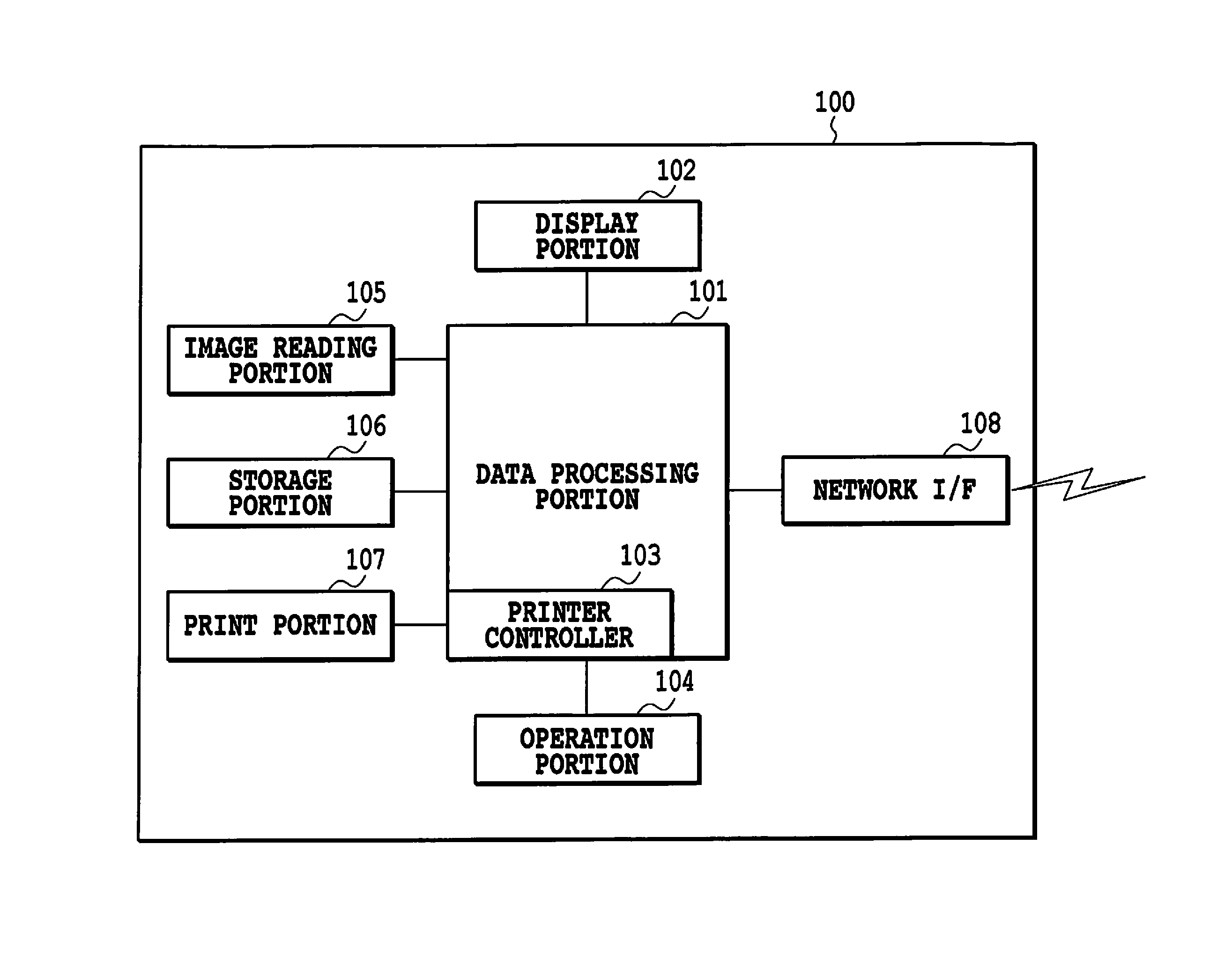
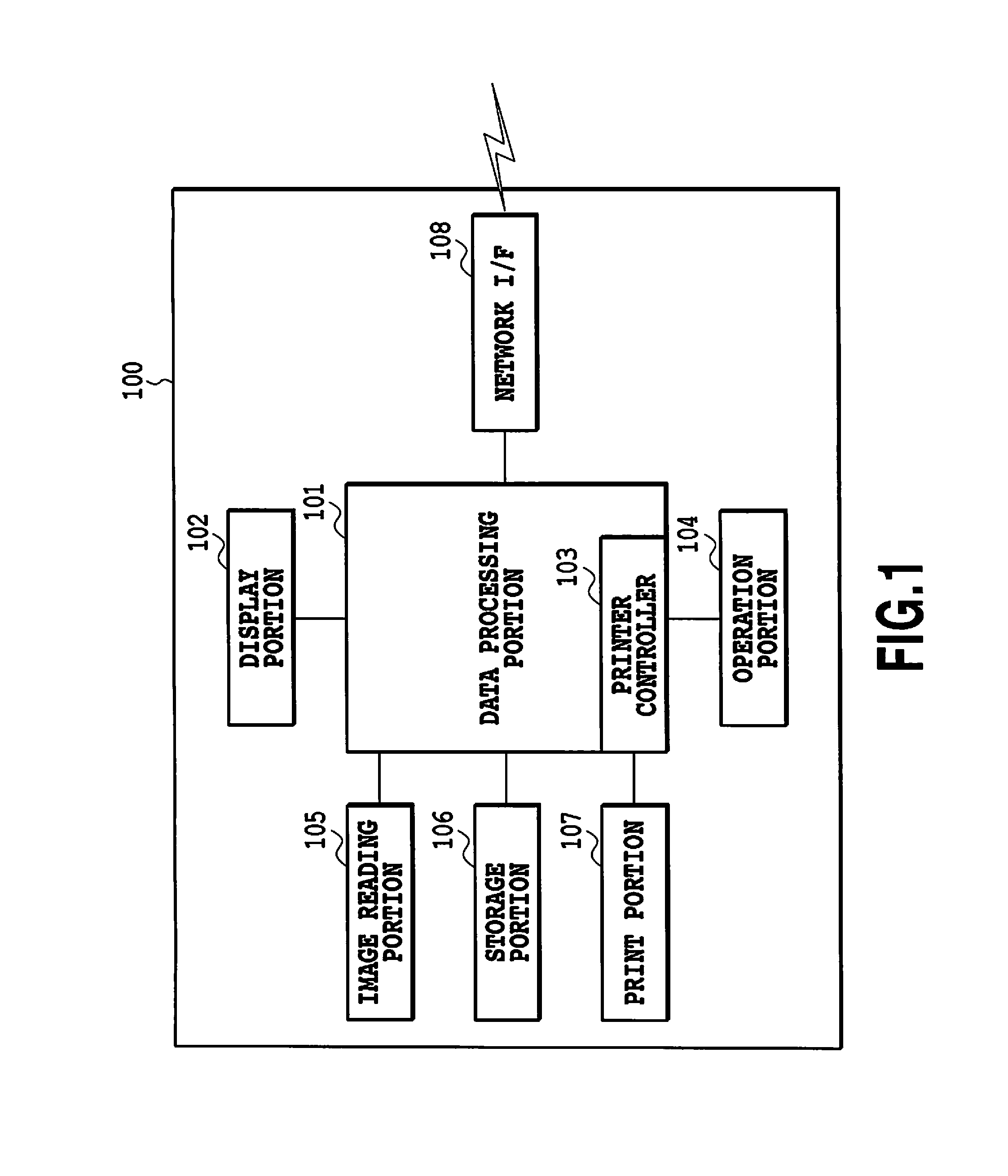
[0030]FIG. 1 is a block diagram illustrating the configuration of a color image forming apparatus 100 according to a first embodiment of the present invention.

[0031]This image forming apparatus 100 is configured with, for example, a multi-function peripheral (MFP) which is a composite device achieving a plurality of types of functions. The image forming apparatus 100 is connected through a network I / F 108 to a network, utilizes the network and can thereby exchange various types of information such as image data with an external device connected to the network.

[0032]In FIG. 1, an image reading portion 105 including a platen and an auto document feeder (ADF) illuminates, with a light source, stacked sheets of or a sheet of original document image on the platen, and forms, with a lens, an image reflected off the document on a solid-state image pickup element (not shown). Thus, the image reading portion 105 can obtain a raster-shaped image reading signal from the solid-state image picku...

second embodiment

[0065]A description has been given of the example where the low resolution correction processing portion 404 takes over the second memory 406 in the image correction portion 305 shown in FIG. 4. The image memory 304 and the second memory 406 are often included as an external memory device of an integral circuit device such as an ASIC. When a large number of components are required as described above, the number of components is increased, and this leads to the increase in the cost. Hence, in the second embodiment, a description will be given of a case where the second memory 406 and the image memory 304 are shared.

[0066]FIG. 7 is a diagram showing a configuration in which one region of the image memory 304 is used as the second memory 406. The low resolution correction processing portion 404 shown in FIG. 7 reads and writes bitmap data through a system bus 311, and thereby performs the low resolution correction processing.

third embodiment

[0067]In the first and second embodiments, a description has been given of the example where the nigh resolution correction processing is performed on the upstream side of the image correction portion, and the low resolution correction processing is performed on the data that has been subjected to the high resolution correction processing. However, a configuration in which the second memory 406 and the image memory 304 are shared and the order of connection between the low resolution correction processing portion 404 and the high resolution correction processing portion 403 is changed can be considered. FIG. 8 is a diagram showing such a configuration. In the low resolution correction processing portion 404 shown in FIG. 4, the input bitmap data is first written in the second memory 406, and, when it is then read, the read address is changed based on RegSegPosL[i]. When the low resolution correction processing portion 404 shown in FIG. 8 reads the image data from the image memory 30...


PUM


Abstract

Since memory access is performed on a large number or discontinuous address regions, the performance of memory access is significantly degraded; in a system that performs high speed image formation, registration deviation cannot be corrected. Sub scanning position information corresponding to the profile of registration deviation is set, and image correction processing is divided into two stages, high resolution correction processing using line buffers formed with a memory which allows high speed random access and low resolution correction processing using a memory whose capacity is easily increased.

Description

BACKGROUND OF THE INVENTION[0001]1. Field of the Invention[0002]The present invention relates to an image forming apparatus and an image forming method for correcting registration deviation caused when an image is formed.[0003]2. Description of the Related Art[0004]In recent years, in order to increase the image formation speed of an electrophotographic color image forming apparatus (laser printer), a large number of color image forming apparatuses of a tandem system have been employed. In the tandem system, the same number of developing devices and photoconductive drums as the number of kinds of color materials (toners) are arranged, and images of different colors are sequentially transferred onto a conveyor belt or a recording sheet, and thus a color image is formed. In this type of tandem system color image forming apparatus, since the images of different colors are formed by image formation portions corresponding to those colors, a plurality of factors that causes registration d...

Claims


Application Information

Patent Timeline
Patent Type & Authority Patents(United States)
IPC IPC(8): G03G15/01H04N1/04H04N1/60H04N1/047
CPCG03G15/0178H04N1/0473H04N1/603H04N2201/04791H04N2201/04793H04N2201/04796G03G2215/0119G03G2215/0161H04N2201/0094H04N2201/04787
Inventor MORITA, SEIJIRO
Owner CANON KK
Why Eureka
Try Eureka