Shape measuring instrument, impedance detector, and impedance detection method
a technology of shape measurement and detector, applied in the direction of instruments, resistance/reactance/impedence, electric/magnetic measuring arrangements, etc., can solve the problems of increasing impedance, increasing distortion, increasing impedance in the cable, etc., and achieve the effect of easy detection of impedan
- Summary
- Abstract
- Description
- Claims
- Application Information
AI Technical Summary
Benefits of technology
Problems solved by technology
Method used
Image

Examples
embodiment 1
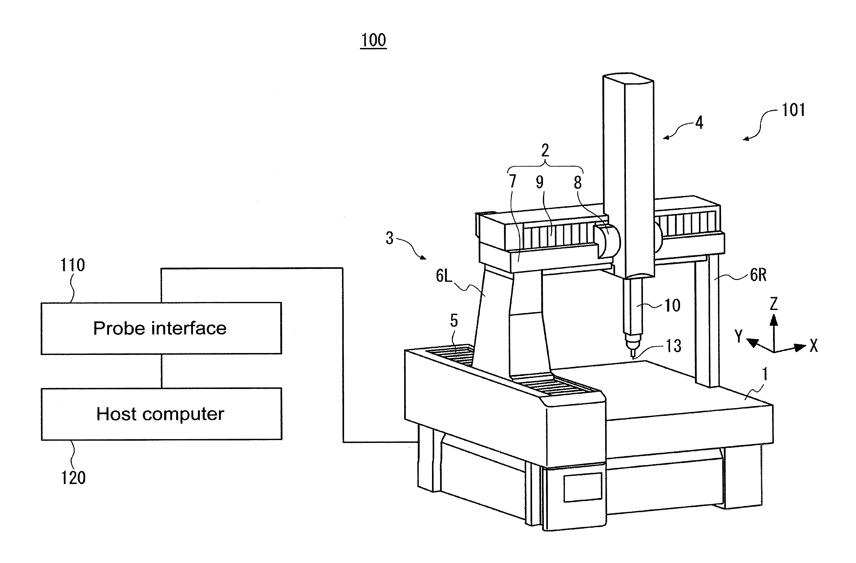
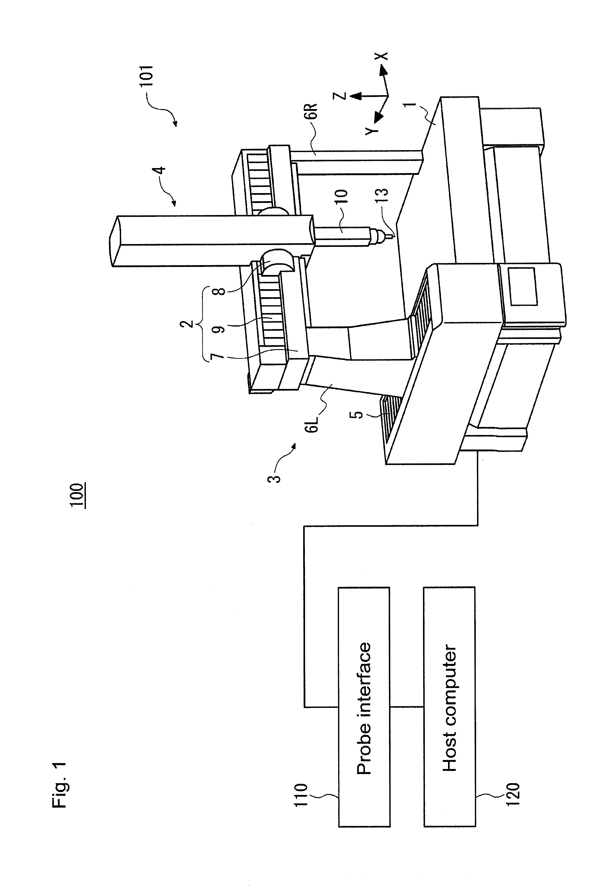
[0048]First, a description is given of a shape measuring instrument 100 according to Embodiment 1. FIG. 1 schematically illustrates a configuration of the shape measuring instrument 100 according to Embodiment 1. The shape measuring instrument 100 includes a coordinate measuring device 101, a probe interface 110, and a host computer 120. Hereafter, the probe interface 110 is also referred to as a control device. The coordinate measuring device is also referred to simply as a measuring device.
[0049]The coordinate measuring device 101 includes a displacement mechanism provided on a table 1, the displacement mechanism displacing a probe 13. A work piece is placed on the table 1. Hereafter, the probe 13 is also referred to as a movable detector or as a movable portion. The displacement mechanism is configured by an X-direction drive mechanism 2, a Y-direction drive mechanism 3, and a Z-direction drive mechanism 4. The X-direction drive mechanism 2 displaces the probe 13 in an X directio...
embodiment 2
[0089]Next, a description is given of a shape measuring instrument 200 according to Embodiment 2. FIG. 6 is a block diagram schematically illustrating a configuration of the shape measuring instrument 200 according to Embodiment 2. The shape measuring instrument 200 has an additional cable 13B, as compared to the shape measuring instrument 100. The cable 13B is connected between the probe interface 110 and the probe 13. The cable 13B is a cable for performing communication at a lower speed than the cable 13A. Other configurations of the shape measuring instrument 200 are similar to those of the shape measuring instrument 100 and descriptions thereof are therefore omitted.
[0090]Next, a description is given of a test operation for impedance in the cable of the coordinate measuring device according to the present embodiment. Similar to the shape measuring instrument 100, the shape measuring instrument 200 can perform the test operation for impedance using the high-speed test data TH th...
embodiment 3
[0096]Next, a description is given of a shape measuring instrument 300 according to Embodiment 3. FIG. 8 is a block diagram schematically illustrating a configuration of the shape measuring instrument 300 according to Embodiment 3. The shape measuring instrument 300 has additional cables 13C and 13D, as compared to the shape measuring instrument 100. The cables 13C and 13D are connected between the probe interface 110 and the probe 13. The cables 13C and 13D are short-circuited on the interior of the probe 13.
[0097]In addition, the cables 13A, 13C, and 13D are gathered together as a single bundled cable 130. Accordingly, the cables 13A, 13C, and 13D travel along the same pathway, and thus are repeatedly bent the same number of times and to the same degree by repeated shape measurements.
[0098]Next, a description is given of the test operation for impedance in the cable of the coordinate measuring device of the present embodiment. Using the cables 13C and 13D, the shape measuring inst...
PUM
 Abstract
Description
Claims
Application Information