Integrated cooling system and method for engine-powered unit

a technology of integrated cooling system and engine, which is applied in the direction of machines/engines, indirect heat exchangers, light and heating apparatus, etc., can solve the problems of adding significant weight, volume and cost to the cooling system as a whol

Inactive Publication Date: 2014-05-08
GE GLOBAL SOURCING LLC
View PDF19 Cites 18 Cited by
  • Summary
  • Abstract
  • Description
  • Claims
  • Application Information

AI Technical Summary

Problems solved by technology

As will be readily appreciated, however, having two separate cooling loops, each with a dedicated radiator and cooling fan, adds significant weight, volume and cost to the cooling system, as a whole.

Method used


Image

  • Integrated cooling system and method for engine-powered unit
  • Integrated cooling system and method for engine-powered unit
  • Integrated cooling system and method for engine-powered unit

Examples


Embodiment Construction

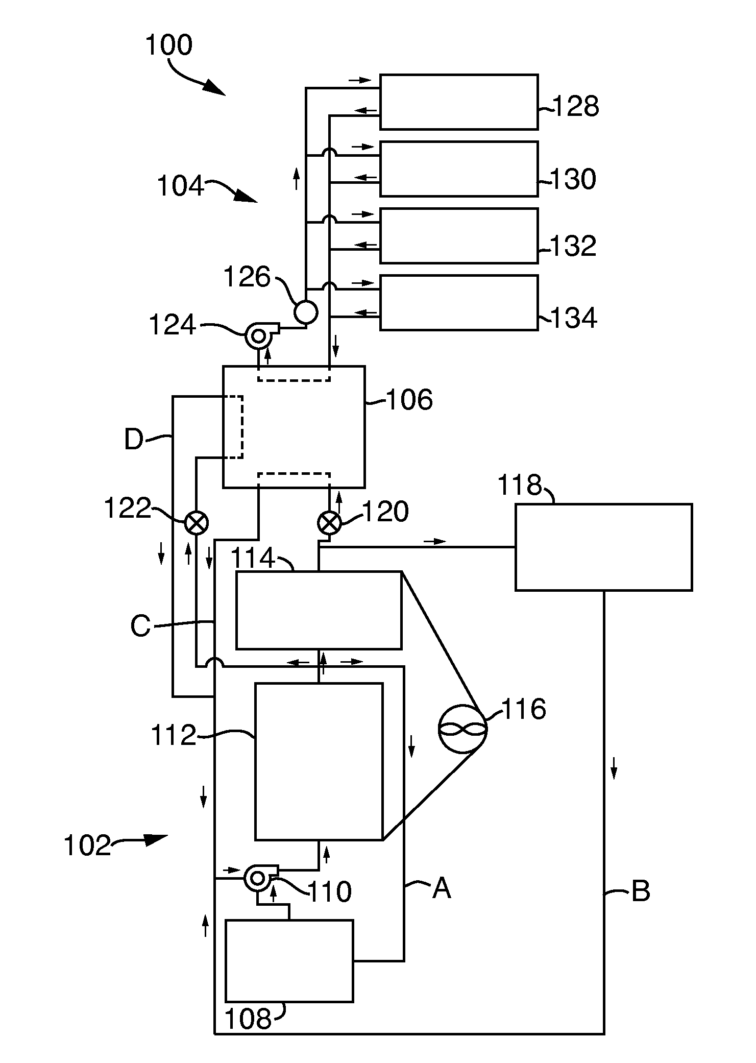
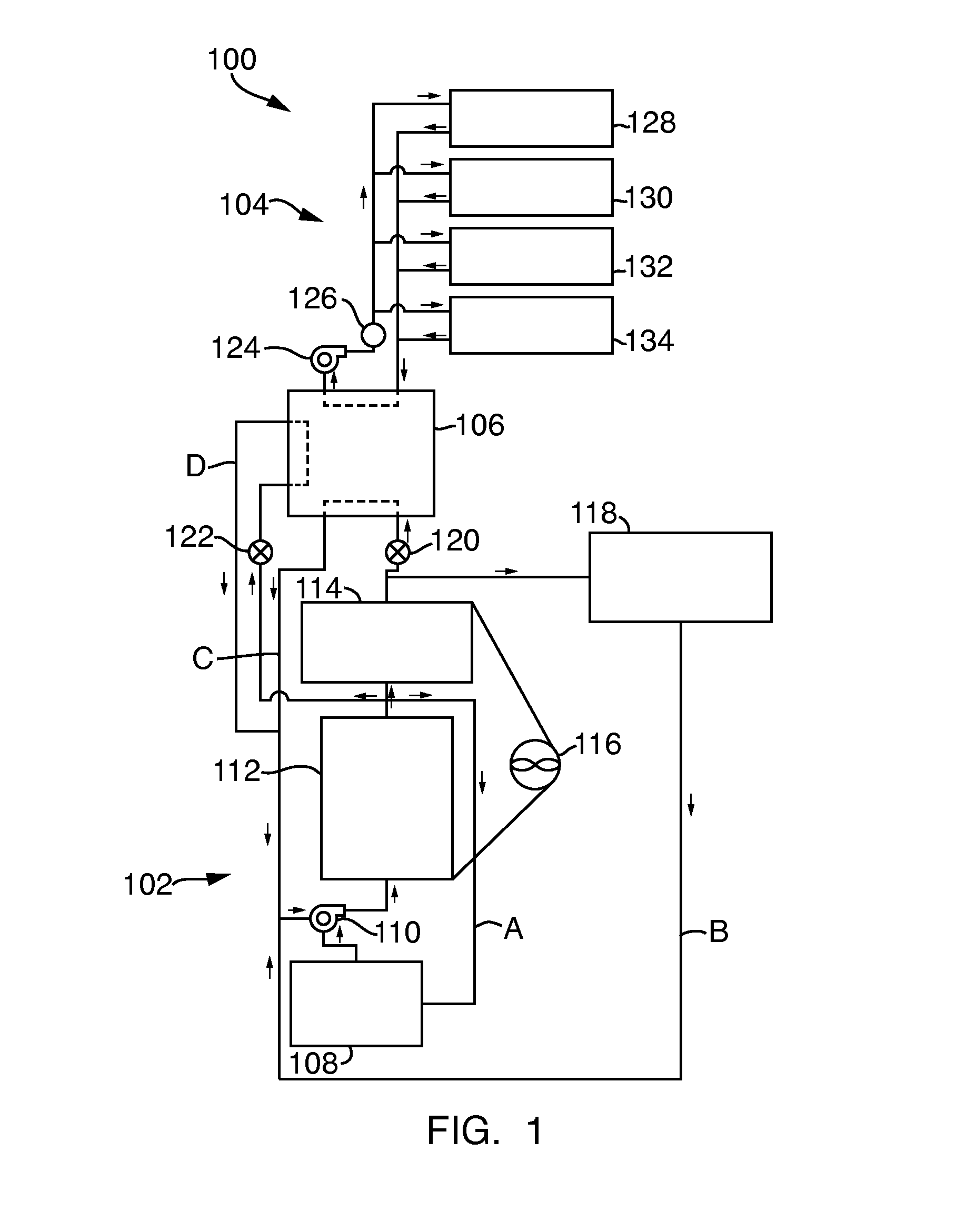
[0014]Reference will be made below in detail to exemplary embodiments of the invention, examples of which are illustrated in the accompanying drawings. Wherever possible, the same reference numerals used throughout the drawings refer to the same or like parts. Although exemplary embodiments of the present invention are described with respect to rail vehicles and other OHVs, embodiments of the invention are also applicable for use with vehicles, generally. In addition, embodiments of the present invention are equally applicable to any type of machinery, motive or non-motive, that includes an internal combustion engine and any other auxiliary components that require cooling, such as associated power electronics. (As noted above, such vehicles and other machinery are referred to herein as engine-powered units.) For example, the embodiments of the present invention are applicable to underground machinery utilized in the mining industry, having dedicated power electronics, as well as to ...


PUM


Abstract

The present invention relates to an integrated cooling system for a vehicle. The system includes an engine cooling loop having a first fluid configured for circulation through an engine of the vehicle and a power electronics cooling loop having a second fluid configured for circulation through at least one power electronics component of the vehicle. The engine cooling loop is fluidly isolated from, and in thermal communication with, the power electronics cooling loop.

Description

FIELD OF THE INVENTION[0001]Embodiments of the invention relate generally to cooling systems. Other embodiments relate to cooling systems for internal combustion engines and power electronics.BACKGROUND OF THE INVENTION[0002]Most modern rail locomotives are of the diesel-electric variety, in which an internal combustion engine, most often a diesel engine, drives an electrical generator whose output provides power to traction motors to turn the wheels of the locomotive to generate motion. The diesel engine, which is typically a turbocharged diesel engine, requires a cooling system to limit the temperatures of various engine components. Accordingly, internal combustion engines are known to be designed with internal cooling passages for the circulation of coolant to remove heat energy from the engine components and from lubricating oil which is also circulated throughout the engine to reduce friction.[0003]Similarly, other off-highway vehicles (“OHVs”), such as those used in the mining...

Claims


Application Information

Patent Timeline
Patent Type & Authority Applications(United States)
IPC IPC(8): F28D15/00
CPCF01P3/20F01P7/165F01P2050/30F02D29/06B61C7/04B61C17/04F02B29/0443Y02T10/12Y02T30/00
Inventor YOUNG, HENRY TODDKUTTENKULER, JASON DANIELCILLESSEN, SEAN
Owner GE GLOBAL SOURCING LLC
Why Eureka
Try Eureka