Immersion cooling systems and methods

a cooling system and immersion technology, applied in the field of electric systems, can solve the problem that the cooling agents employed in such cooling arrangements can be heavy in comparison to other cooling arrangements

Active Publication Date: 2017-10-05
HAMILTON SUNDSTRAND CORP
View PDF20 Cites 18 Cited by
  • Summary
  • Abstract
  • Description
  • Claims
  • Application Information

AI Technical Summary

Benefits of technology

[0011]In certain embodiments, the method can include heating a liquid-vapor phase dielectric coolant contained within a sealed housing using an electronic device submerged within the coolant. The method can include transferring heat from the liquid-vapor phase coolant into a solid-liquid PCM disposed within the dielectric coolant.

Problems solved by technology

The coolants employed in such cooling arrangements can

Method used


Image

  • Immersion cooling systems and methods
  • Immersion cooling systems and methods
  • Immersion cooling systems and methods

Examples


Embodiment Construction

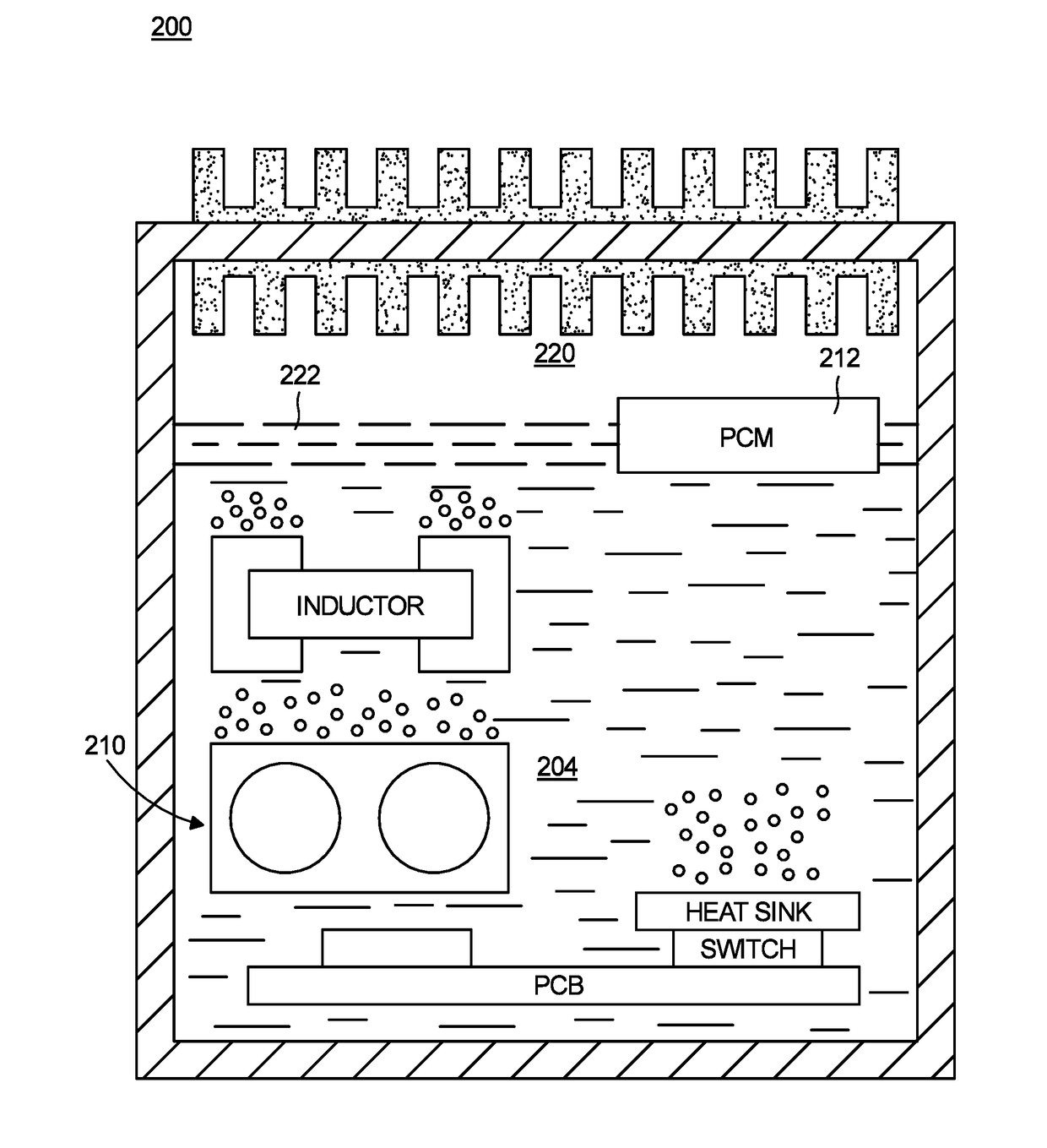
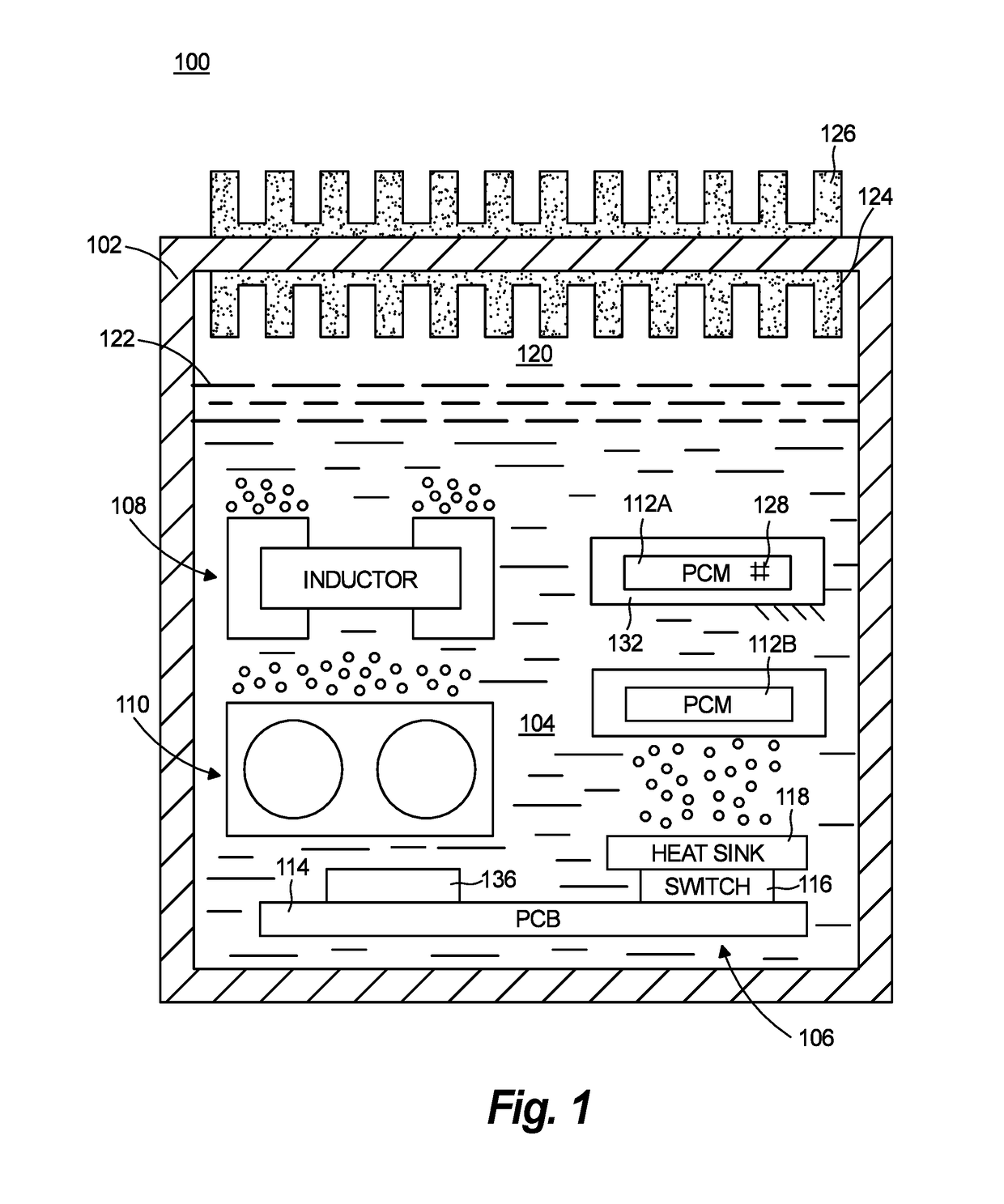
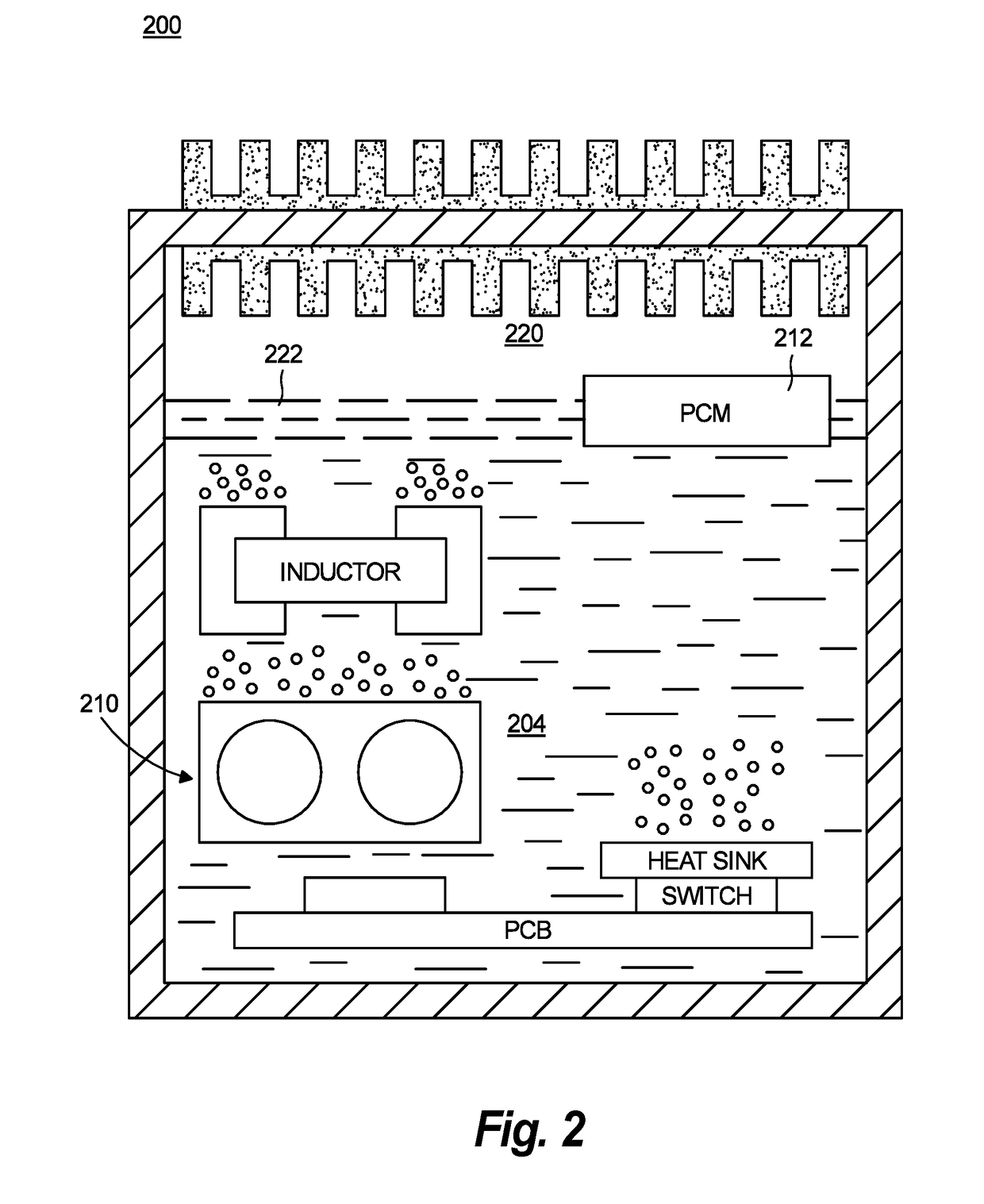
[0017]Reference will now be made to the drawings wherein like reference numerals identify similar structural features or aspects of the subject disclosure. For purposes of explanation and illustration, and not limitation, a partial view of an exemplary embodiment of an electronics cooling arrangement in accordance with the disclosure is shown in FIG. 1 and is designated generally by reference character 100. Other embodiments of electronics cooling arrangements, immersion cooled electronic assemblies, and methods of removing heat from such arrangements and assemblies in accordance with the disclosure, or aspects thereof, are provided in FIGS. 2 and 3, as will be described. The systems and methods described herein can be used in vehicle electrical systems, such as in motor controllers and / or power converters, though the present disclosure is not limited power converters, motor controllers, or to vehicular electrical systems in general.

[0018]Referring to FIG. 1, electronics cooling arr...


PUM


Abstract

An electronics cooling arrangement includes a housing, an electronic device disposed within the housing, and a solid-liquid phase change material disposed within the housing and is in thermal communication with the electronic device to absorb heat generated by the electronic device. A method of cooling an electronic device and a vehicular electronics cooling system are also described.

Description

BACKGROUND OF THE INVENTION1. Field of the Invention[0001]The present disclosure relates to electrical systems, and more particularly to cooling arrangements for electronic devices in electrical systems.2. Description of Related Art[0002]Electrical power systems commonly include devices like solid-state power converters, motor controllers, and battery charging modules. Such devices generate heat during operation from electrical power applied to the devices, which typically is removed using a cooling arrangement. The cooling arrangement is generally selected according to the amount of heat that the device generates during operation, examples of cooling arrangements including conduction cooling, natural convection cooling, radiation cooling, forced-air cooling, and liquid cooling.[0003]With the advent of the ‘more electric’ vehicles, power systems increasingly employ electronic devices with increased power densities. The increased power densities of such electronic devices can be acco...

Claims


Application Information

Patent Timeline
IPC IPC(8): H05K7/20
CPCH05K7/203H05K7/20936
Inventor SHEPARD, CHARLESCAMPBELL, KRIS H.
Owner HAMILTON SUNDSTRAND CORP
Why Eureka
Try Eureka