Safety sill for a structural frame bearing a batter in the event of a side impact

a safety sill and structural frame technology, applied in the field of safety sills for structural frames, can solve the problems of limited material choice for load transmission elements, weight reduction cannot be achieved at the expense of body characteristics in terms of stability, and the inability to insertion load transmission elements after immersion paint coating, etc., to achieve the effect of reducing weight, saving materials, and expanding options

Inactive Publication Date: 2014-05-08
RACHFAHL JOACHIM
View PDF2 Cites 4 Cited by
  • Summary
  • Abstract
  • Description
  • Claims
  • Application Information

AI Technical Summary

Benefits of technology

[0006]The present application achieves a reduction in weight while at the same time achieving savings in the use of materials, to expand the options in the selection of materials, to make possible the use of a mixture of materials, for example steel and aluminium, in other words a hybrid construction, to overcome the disadvantages stated, and to improve the interaction between support elements and sills.
[0011]In order to fix a sill element inserted against or into the support element after the customary immersion paint coating, it is advantageous to use a fastening technique that does not require the use of warmth or heat as would be the case in welding techniques. It is thus preferred to interconnect the support element and the sill element by means of adhesive bonding or screwing. In particular in the case of fixing by bonding it is advantageous if all the contact surfaces of the form-lock between the two molded parts are inclined relative to the X-Y-plane of the vehicle body, because frictional engagement on contact surfaces extending parallel to the X-Y-plane, even reinforced by adhesive bonding, in the case of lateral impact loads is considerably less than in the case of correspondingly inclined surfaces.

Problems solved by technology

However, any reduction in weight must not be achieved at the expense of body characteristics in terms of stability, desired rigidity and, last but not least, mountability in the context of robot-supported production lines.
The above is associated with disadvantages in that, as a result of the focus on the static and dynamic requirements, the forms of load transmission elements and the surrounding deformation contour of the sill are as a rule designed so that the deformation contour of the sill needs to be closed before the usual coating by means of cathodic immersion paint coating can take place.
Any insertion of load transmission elements after immersion paint coating is not possible without incurring undesirable disadvantages in the overall production process.
As a result of this the choice of materials for the load transmission elements is limited.
Of course, it is not mandatory to use additional molded parts.

Method used


Image

  • Safety sill for a structural frame bearing a batter in the event of a side impact
  • Safety sill for a structural frame bearing a batter in the event of a side impact
  • Safety sill for a structural frame bearing a batter in the event of a side impact

Examples


Embodiment Construction

[0022]Below, preferred embodiments of the safety sill are explained in more detail with reference to the drawings.

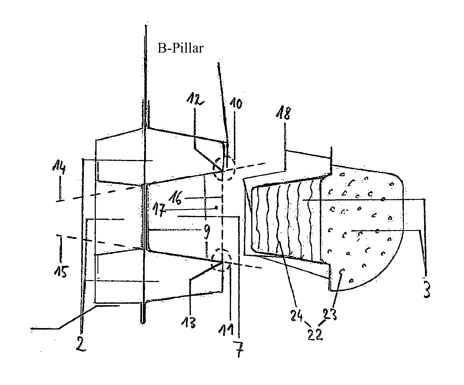
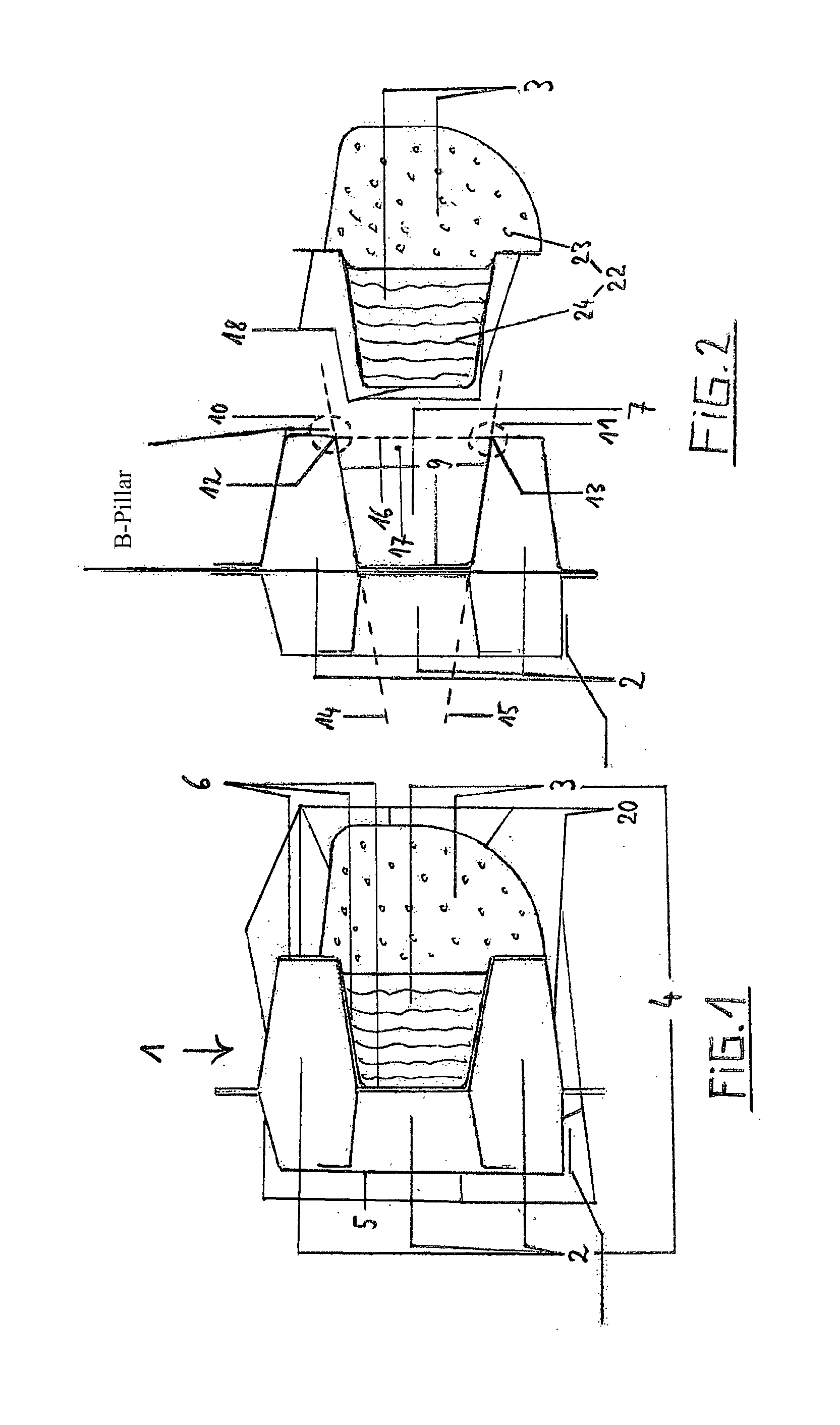
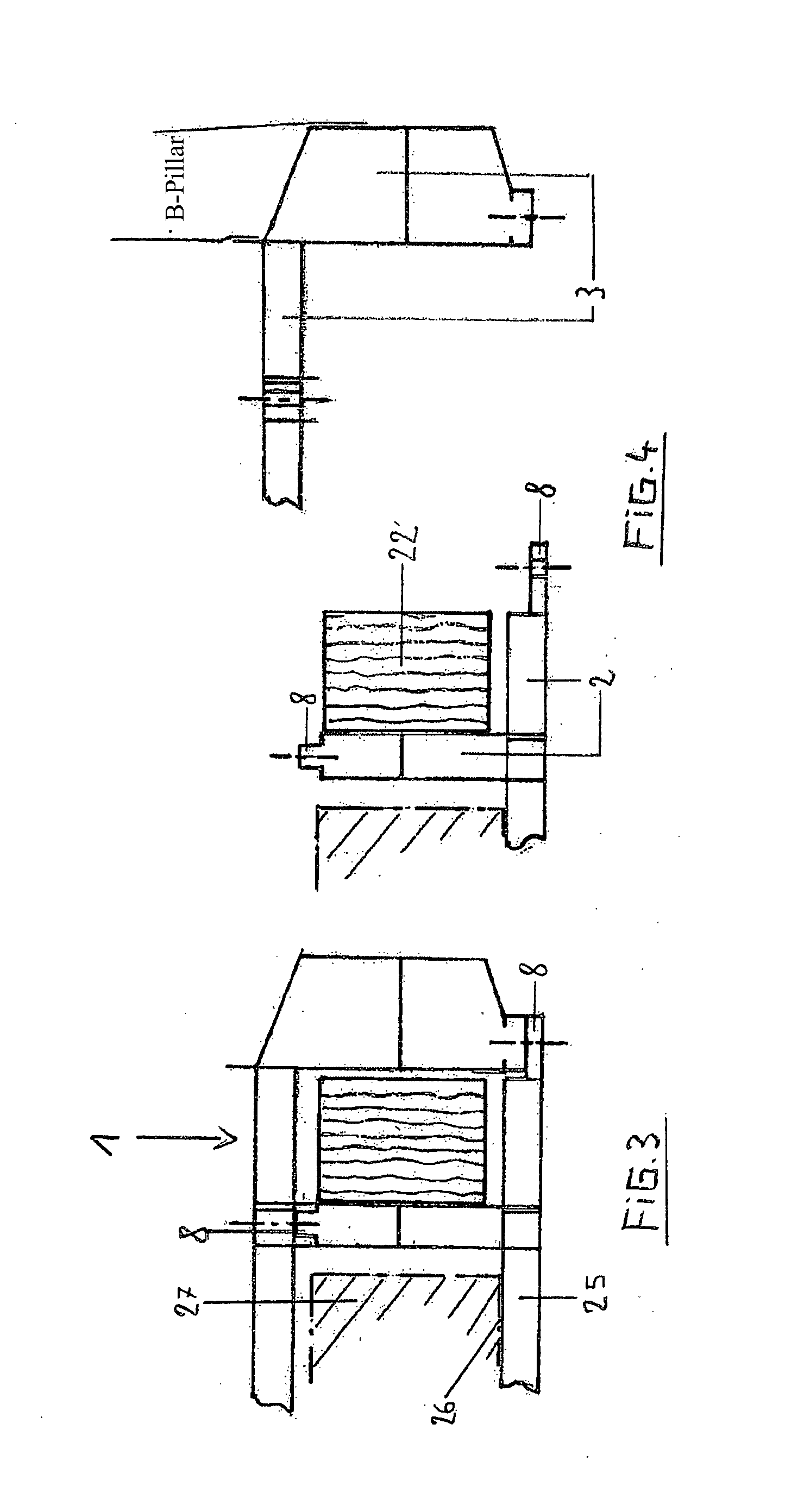
[0023]FIG. 1 shows a cross section of a safety sill (1) that has been joined, by adhesive bonding, from a support element (2) mounted to the body-in-white and a mountable sill element (3). The diagram shows the inside (5) and the outside (6) of the support element (2), wherein the outside (6) in this exemplary embodiment comprises an almost U-shaped cavity (see FIG. 2, cipher 7). By joining the support element (2) with the sill element (3) a body member (4) is constituted that conforms with the safety sill (1), wherein the structural characteristics in this example predominantly result from the support element (2) and the part of the sill element (3), which part fills the cavity (see FIG. 2, cipher 7). The outer jacket surface of the safety sill forms the deformation contour (20), which can also be covered by means of a design panel that can optionally be affixed.

[0024]F...


PUM


Abstract

A safety sill for a vehicle body, which is characterized by at least two molded parts that are connected to one another in a form-closed manner and form a body member, wherein the first load-bearing molded part is a support element having an inside and an outside and the second load-bearing molded part is a sill element, the outside of the support element faces the sill element and either the support element or the sill element can be mounted to the body-in-white and the other load-bearing molded part can be mounted to the molded part mounted to the body-in-white, is provided.

Description

CROSS-REFERENCE TO RELATED APPLICATIONS[0001]This application claims priority to PCT Application No. PCT / DE2012 / 000516, having a filing date of May 21, 2012, pursuant to U.S.C. §365.FIELD OF TECHNOLOGY[0002]The following relates to a safety sill for a structural frame, and more specifically to a safety sill for a vehicle body.BACKGROUND[0003]In motor vehicle body construction it has always been desirable to save weight. However, any reduction in weight must not be achieved at the expense of body characteristics in terms of stability, desired rigidity and, last but not least, mountability in the context of robot-supported production lines. In particular those body regions which because of their stability characteristics in the case of accidents are to absorb the forces that are typically encountered in accidents are the subject of numerous different design efforts. Especially sills and structural members of vehicle bodies have been varied many times.[0004]The principal significance o...

Claims


Application Information

Patent Timeline
Patent Type & Authority Applications(United States)
IPC IPC(8): B62D21/15
CPCB62D21/157
Inventor RACHFAHL, JOACHIM
Owner RACHFAHL JOACHIM
Why Eureka
Try Eureka