Suspension board assembly sheet with circuits and method for manufacturing the same

a suspension board and circuit technology, applied in the field of suspension board assembly sheet with circuits, can solve the problems achieve the effects of low reliability of inspection results, short inspection time period of suspension board plated via portions, and high correlation

Active Publication Date: 2014-05-08
NITTO DENKO CORP
View PDF7 Cites 7 Cited by
  • Summary
  • Abstract
  • Description
  • Claims
  • Application Information

AI Technical Summary

Benefits of technology

[0007]In JP 2012-18984 A, a substrate for suspension with a support frame having an inspecting plated via portion (a plated via portion for inspection) at the support frame is described. According to JP 2012-18984 A, it is possible to perform inspection of a plated via portion of a plurality of suspension boards by performing inspection of the inspecting plated via portion at the support frame without directly respectively inspe

Problems solved by technology

Therefore, reliability of t

Method used


Image

  • Suspension board assembly sheet with circuits and method for manufacturing the same
  • Suspension board assembly sheet with circuits and method for manufacturing the same
  • Suspension board assembly sheet with circuits and method for manufacturing the same

Examples


first modified example

[0096](7) First Modified Example

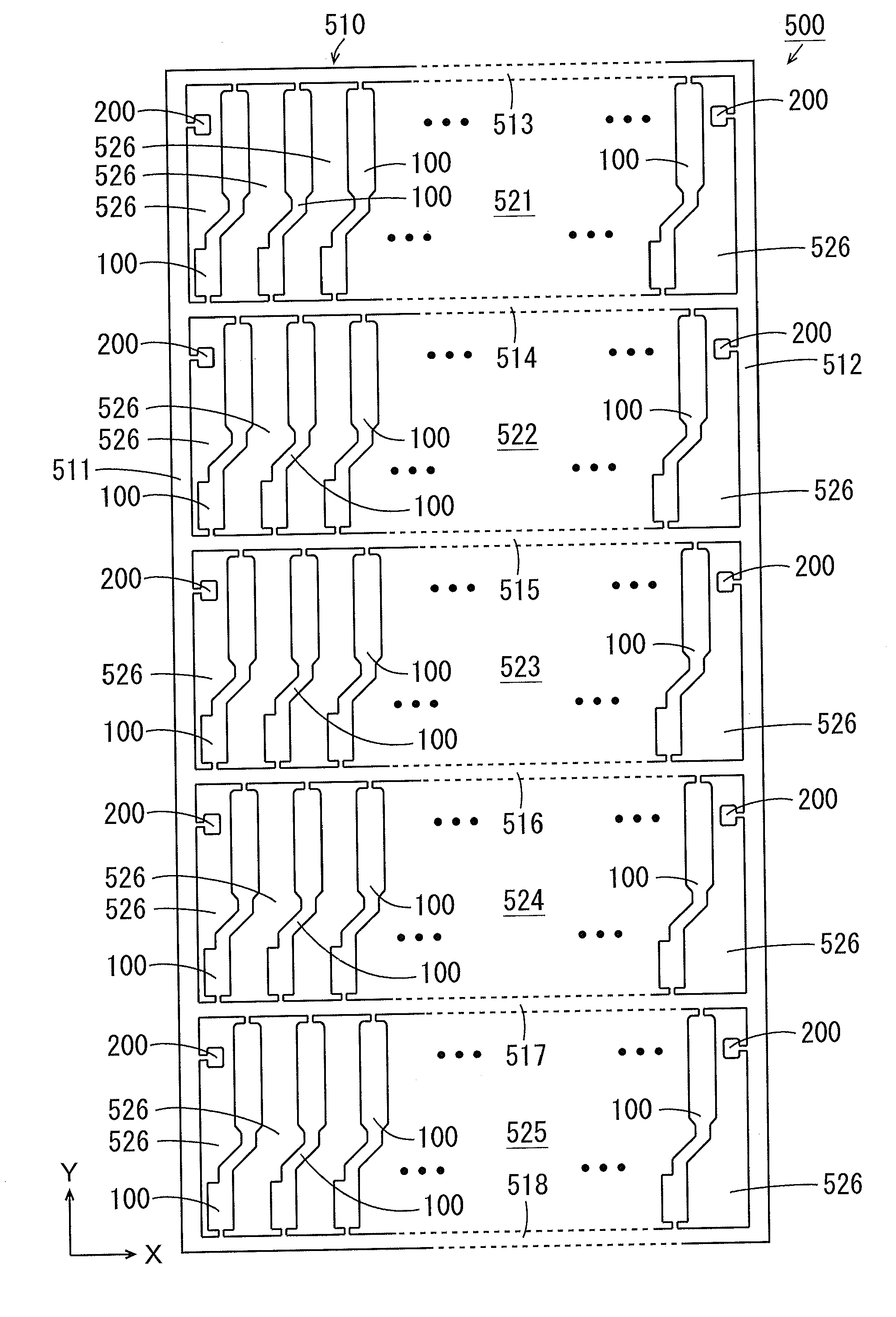
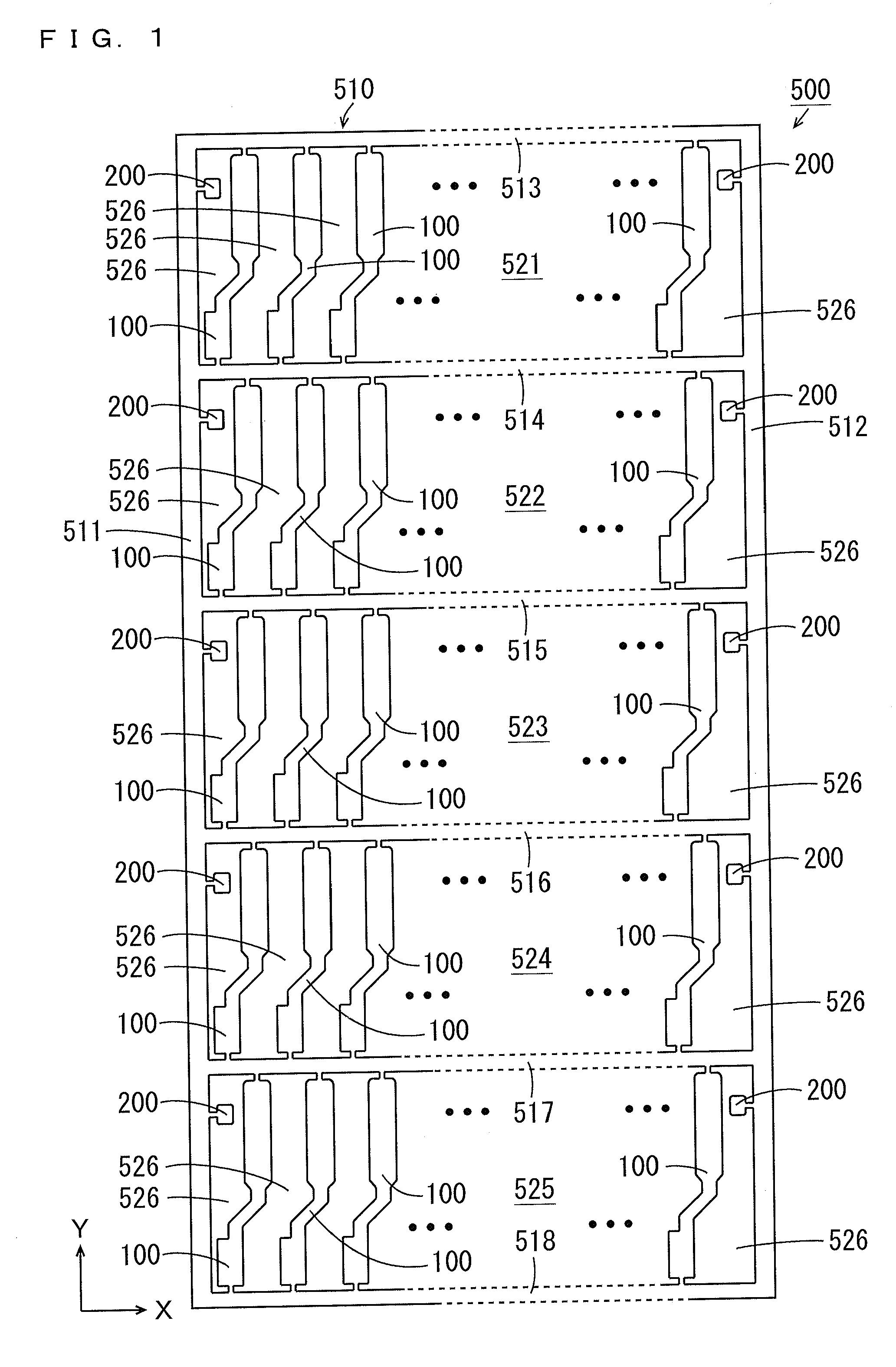
[0097]While the inspection substrate 200 is provided in the separation groove 526 between the suspension board 100 at the one end and the side frame 511, and in the separation groove 526 between the suspension board 100 at the other end and the side frame 512 in each of the rectangular regions 521 to 525 in the X direction in the afore-mentioned embodiment, the invention is not limited to this.

[0098]The inspection substrate 200 may be provided in the separation groove 526 between the suspension substrate 100 at the one end and the side frame 511 in each of the rectangular regions 521 to 525 in the X direction, and the inspection substrate 200 does not have to be provided in the separation groove 526 between the suspension board 100 at the other end and the side frame 512. Alternatively, the inspection substrate 200 may be provided in the separation groove 526 between the suspension board 100 at the other end and the side frame 511 in each of the recta...

second modified example

[0101](8) Second Modified Example

[0102]While the one via 221 is provided at the one inspection substrate 200 in the above-mentioned embodiment, the invention is not limited to this. Multiple types of vias 221 may be provided at the one inspection substrate 200. FIGS. 13(a) and 13(b) are diagrams showing the configuration of the inspection substrate 200 of the assembly sheet 500 according to the second modified example. FIG. 13(a) is a top view of the inspection substrate 200. FIG. 13(b) shows a cross sectional view taken along the line I-I of FIG. 13(a).

[0103]As shown in FIGS. 13(a) and 13(b), in the inspection substrate 200 in the second modified example, one island-shape inner region 241 and another island-shape inner region 241 are formed in an annular opening 244 of the base insulating layer 240. In the one inner region 241, the one via 221 is formed. On the other hand, a plurality (three in this example) of vias 221A, 221B, 221C are formed in another inner region 241.

[0104]In t...


PUM

PropertyMeasurementUnit
Lengthaaaaaaaaaa

Abstract

A plurality of suspension boards and an inspection substrate are integrally supported by a support frame. In each suspension board, a line is formed on a conductive first support substrate via a first insulating layer. The first support substrate and the line are electrically connected by a first via in the first insulating layer. In the inspection substrate, a conductor layer is formed on a conductive second support substrate with a second insulating layer sandwiched therebetween. The second support substrate and the conductor layer are electrically connected by a second via in the second insulating layer. The first via and the second via have the same configuration.

Description

BACKGROUND OF THE INVENTION[0001]1. Field of the Invention[0002]The present invention is related to a suspension board assembly sheet with circuits and a method for manufacturing the suspension board assembly sheet with circuits.[0003]2. Description of Related Art[0004]Actuators are used in drives such as hard disk drives. Such an actuator includes an arm provided rotatably around a rotation shaft, and a suspension board with circuits (hereinafter referred to as a suspension board) for a magnetic head that is attached to the arm. The suspension board is a printed circuit board for positioning the magnetic head at a desired track of a magnetic disk.[0005]The suspension board includes the magnetic head and is connected to another electronic circuit. A conductor pattern is formed at the suspension board, and an electric signal is transmitted between another electronic circuit and the magnetic head through the conductor pattern. The plurality of suspension boards having such configurati...

Claims


Application Information

Patent Timeline
IPC IPC(8): H05K7/02H05K3/10
CPCH05K3/10H05K7/02G11B5/486H05K1/0228H05K1/0245H05K1/025H05K1/0265H05K1/056H05K3/0097H05K3/06H05K3/4685H05K2201/09236H05K2201/09254H05K2201/09509H05K2201/09554H05K2201/09627H05K2201/0979H05K2203/0323Y10T29/49155
Inventor IHARA, TERUKAZUISHII, JUNTERADA, NAOHIRO
Owner NITTO DENKO CORP
Why Eureka
Try Eureka