Communication system and network relay device

a communication system and relay technology, applied in the field of communication system and network relay device, can solve problems such as difficulty in ensuring redundancy and signal loopback, and achieve the effect of preventing signal loopback and improving fault toleran

Active Publication Date: 2014-05-08
APRESIA SYST LTD
View PDF3 Cites 13 Cited by
  • Summary
  • Abstract
  • Description
  • Claims
  • Application Information

AI Technical Summary

Benefits of technology

[0013]Describing in simple terms the advantages obtained by the representative embodiments from among the inventions

Problems solved by technology

However, although it is possible for redundancy to be ensured in a box-type fabric system by means of the aforementioned link aggregation functionality when, for example, a fault has occurred i

Method used


Image

  • Communication system and network relay device
  • Communication system and network relay device
  • Communication system and network relay device

Examples


embodiment 1

[0026]First, prior to a description of a communication system according to the present embodiment 1, matters that were investigated as antecedents thereto will be described using FIG. 8 and FIG. 9.

>

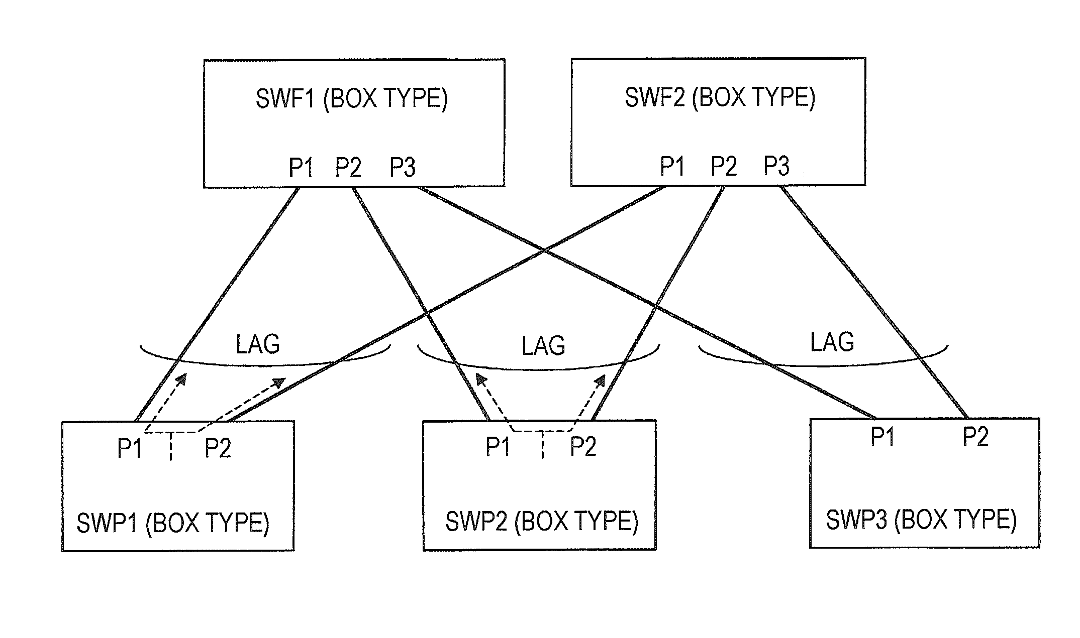
[0027]FIG. 8 is a schematic diagram illustrating an exemplary configuration of a box-type fabric system investigated as an antecedent to the present invention. As depicted in FIG. 8, a box-type fabric system is provided with a plurality of port switches SWP1 to SWP3 (three port switches in this case) that are box-type switch devices, and a plurality of fabric switches SWF1 and SWF2 (two fabric switches in this case) that are box-type switch devices. SWF1 and SWF2 construct communication paths among SWP1 to SWP3.

[0028]Each of the port switches SWP1 to SWP3 is connected to each of the fabric switches SWF1 and SWF2 via different communication lines. Specifically, port P1 and port P2 of SWP1 are connected to each of port P1 of SWF1 and port P1 of SWF2 via different communication lines. Furthe...

embodiment 2

>

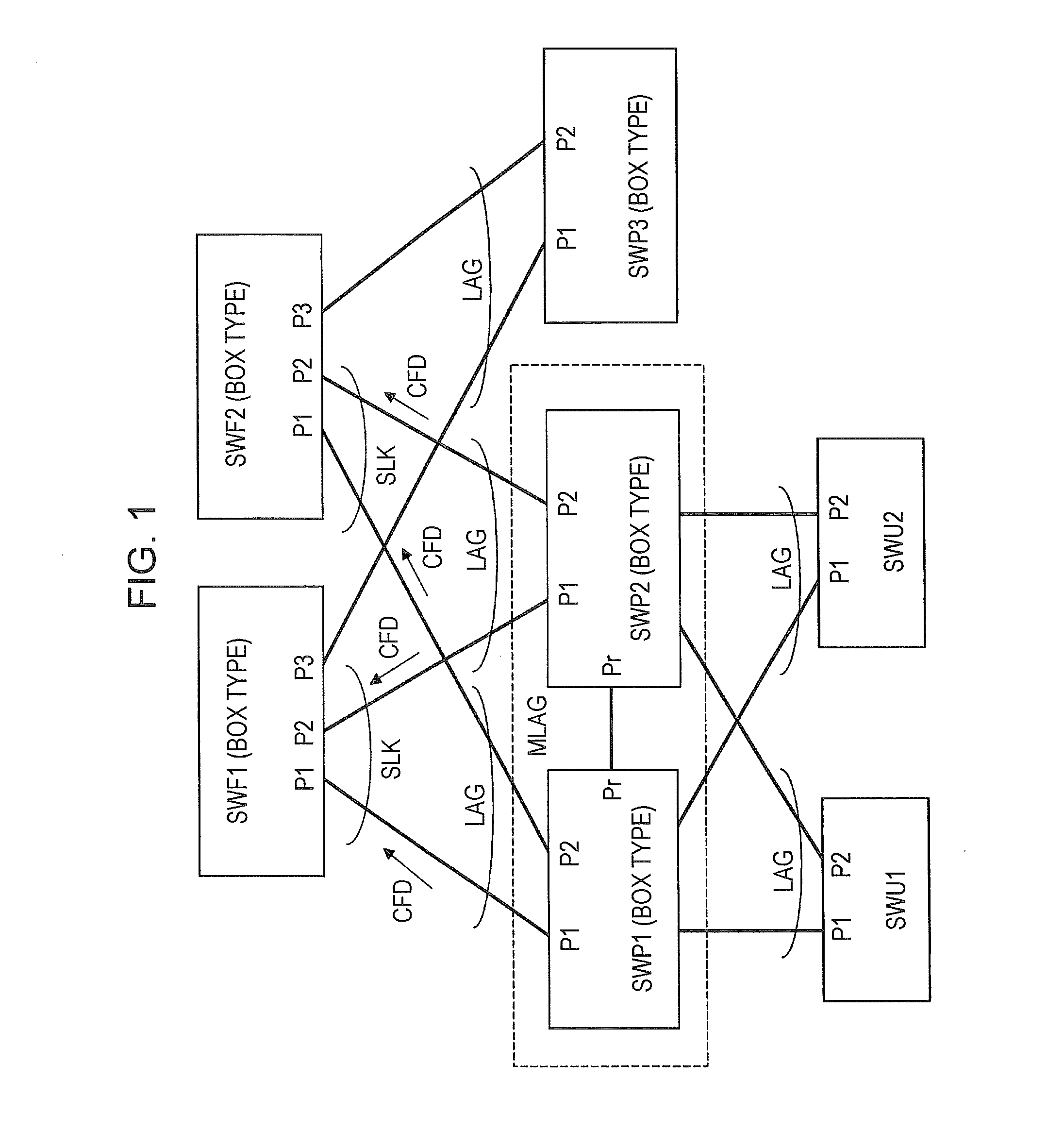
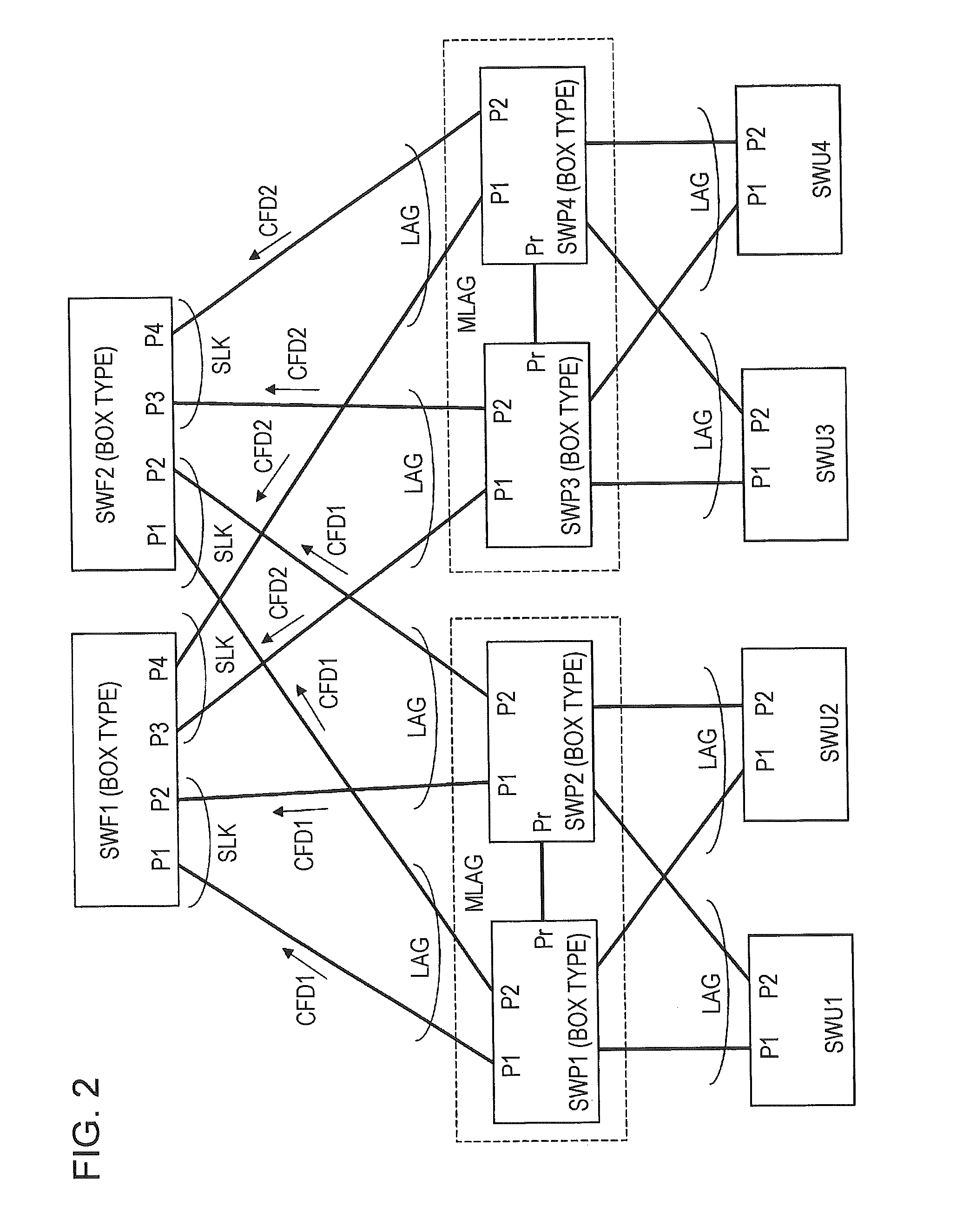
[0060]FIG. 7 is a schematic diagram illustrating an exemplary configuration and a main exemplary operation in a communication system according to embodiment 2 of the present invention. The communication system depicted in FIG. 7 is provided with, as in the aforementioned exemplary configuration of FIG. 1, a plurality (two in this case) of fabric switches (network relay devices) SWF1 and SWF2, a plurality (three in this case) of port switches (network relay devices) SWP1 to SWP3, and user switches SWU1 and SWU2. However, the communication system of FIG. 7 is different from the exemplary configuration of FIG. 1 in that the communication lines between SWP1 to SWP3 and SWF1 to SWF2 are each constituted by pairs of communication lines.

[0061]Together with this, each of the port switches SWP1 to SWP3 of FIG. 7 are provided with a pair of ports P1a and P1b instead of the one port P1 in FIG. 1, and are provided with a pair of ports P2a and P2b instead of the one port P2 in FIG. 1. Likewise,...


PUM


Abstract

In order to provide a communication system and a communication system processing method with which fault resistance is improved and also signal loopback can be prevented, a communication system is provided with, for example, port switches SWP1 to SWP3, fabric switches SWF1 and SWF2, and user switches SWU1 and SWU2, and SWP1 and SWP2 are connected by a common communication line between redundancy ports Pr to thereby form the same domain group (MLAG) and logically function as one switch. Each of SWF1 and SWF2 sets, for ports P1 and P2 to which SWP1 and SWP2 that are constituent elements of the same domain group are connected, a sublink SLK that causes the ports P1 and P2 to logically function as one port.

Description

[0001]The present application is based on Japanese patent application No. 2012-246650 filed on Nov. 8, 2012, the entire contents of which are incorporated herein by reference.BACKGROUND OF THE INVENTION[0002]1. Field of the Invention[0003]The present invention relates to a communication system and a network relay device, and, for example, relates to effective technology applied to a communication system in which link aggregation technology between a network relay device and a plurality of network relay devices is incorporated in part of a system constituted by a plurality of network relay devices.[0004]2. Description of the Related Art[0005]For example, Japanese Unexamined Patent Application Publication No. 2008-78893 discloses a configuration provided with a pair of box-type switch devices that are connected by means of redundancy ports, and edge switches (box-type switches) and an aggregation switch (chassis-type switch) that are connected to the pair of box-type switch devices. T...

Claims


Application Information

Patent Timeline
IPC IPC(8): H04L12/24H04L45/24H04L69/40
CPCH04L41/0668H04L49/25H04L49/111H04L49/10
Inventor TATSUMI, TOMOYOSHIKUMAGAI, WATARU
Owner APRESIA SYST LTD
Why Eureka
Try Eureka