
Systems and methods for monitoring and controlling an electron beam

a technology of electron beam and system, applied in the direction of x-ray tube structural circuit elements, basic electric elements, electric discharge tubes, etc., can solve the problems of x-ray tube not working properly, affecting the operation of the x-ray tube, and damage to the length or pipe of the tub

Active Publication Date: 2014-05-08
GENERAL ELECTRIC CO
View PDF6 Cites 14 Cited by
  • Summary
  • Abstract
  • Description
  • Claims
  • Application Information

AI Technical Summary

Benefits of technology

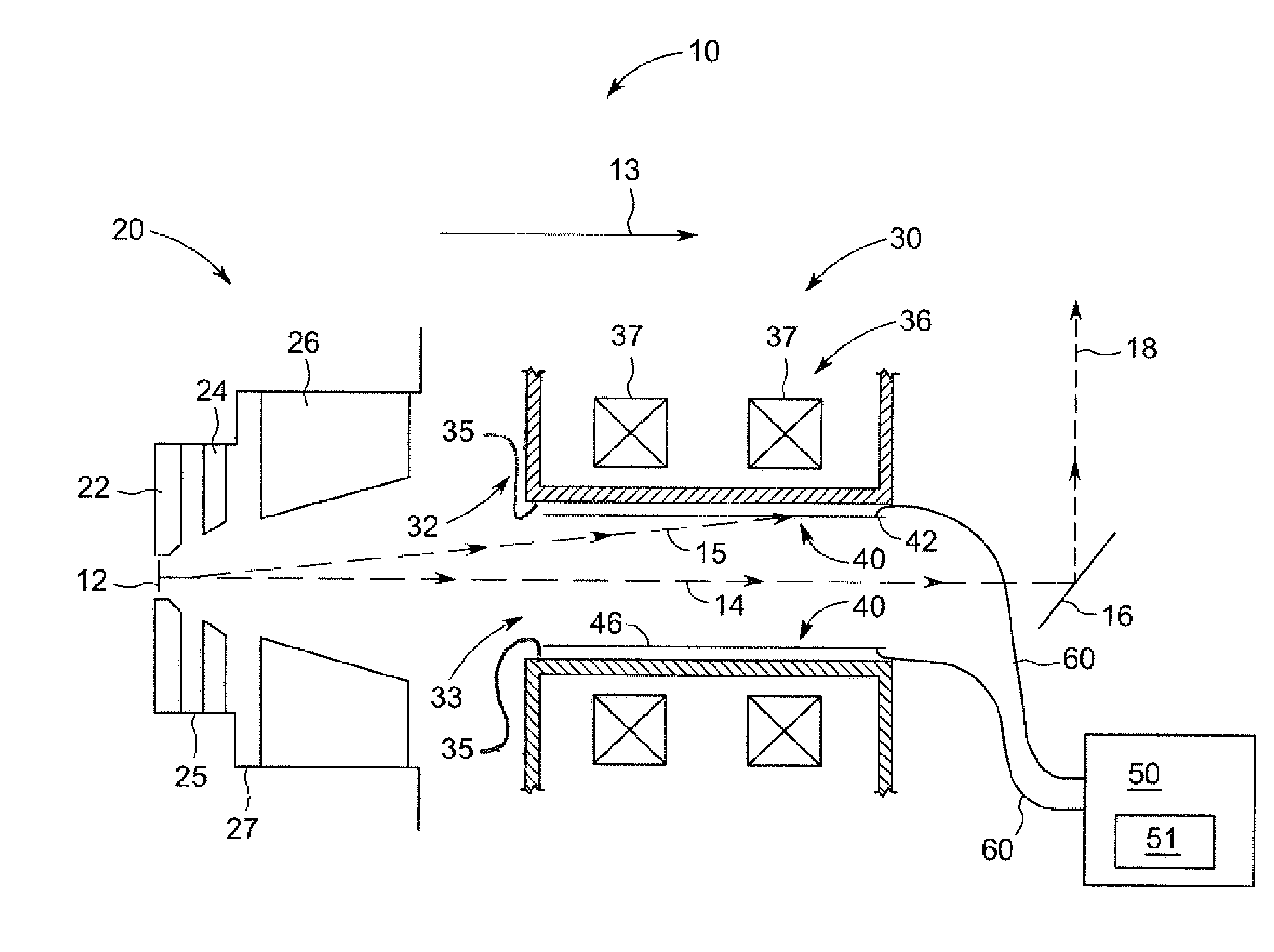
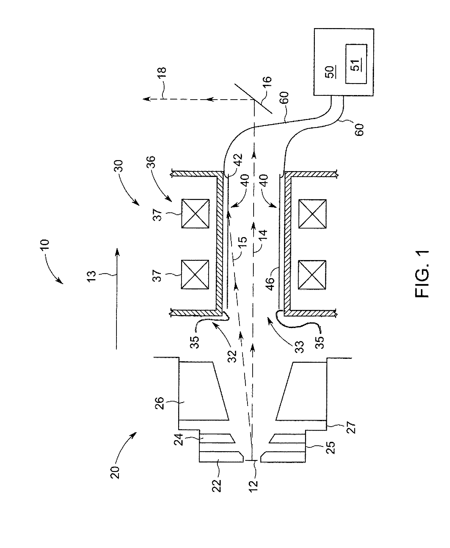
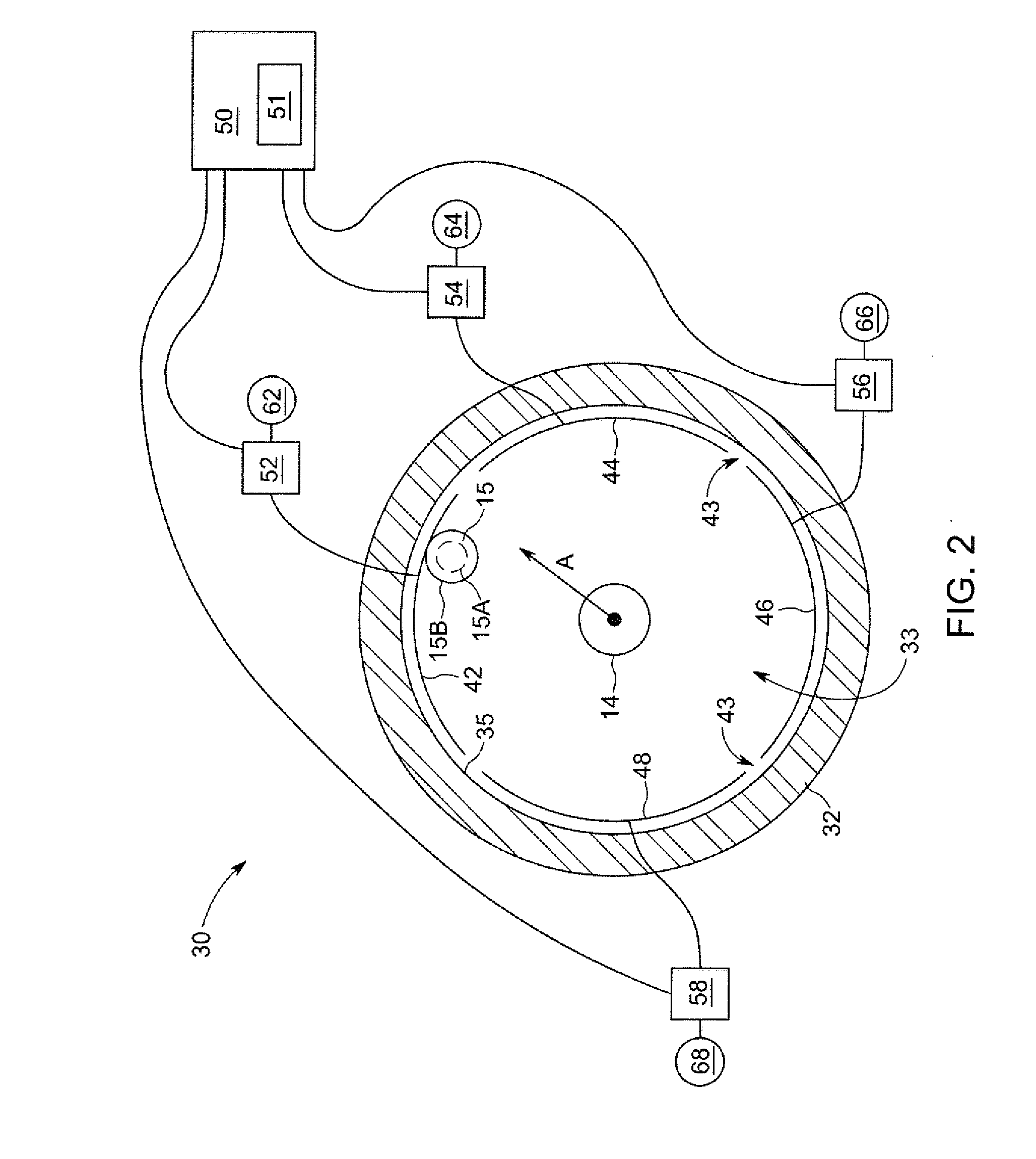
The patent describes an X-ray tube assembly with a beam transport tube, beam tube protection assembly, and control module. The beam transport tube is designed to protect the inner surface from contact with the electron beam and is interposed between the emitter and target. The beam protection assembly includes a plurality of electrodes that collect information about the electron beam as it passes through the electron beam transport tube. The control module analyzes this information to determine the direction of the electron beam. The technical effect of this invention is to provide a more efficient and accurate electron beam for X-ray generation.

Problems solved by technology

Because of the energy present in the electron beam, the electron beam may cause serious damage to the length or pipe of tube through which the electron beam passes if the electron beam strikes the interior of the length of pipe or tube.
For example, if the pipe or tube becomes punctured, breached, or otherwise damaged or compromised, the vacuum within the pipe or tube may be lost and the X-ray tube may not function properly.
Repair and replacement of the tube, or a vacuum casing which the tube forms a part of may be time consuming and expensive.
Problems associated with a mis-aligned electron beam striking the inside of the pipe or tube occur more frequently and / or are exacerbated by these increased lengths of tubes or pipes through which electron beams travel.

Method used


Image

  • Systems and methods for monitoring and controlling an electron beam
  • Systems and methods for monitoring and controlling an electron beam
  • Systems and methods for monitoring and controlling an electron beam

Examples


Embodiment Construction

[0014]Various embodiments will be better understood when read in conjunction with the appended drawings. To the extent that the figures illustrate diagrams of the functional blocks of various embodiments, the functional blocks are not necessarily indicative of the division between hardware circuitry. Thus, for example, one or more of the functional blocks (e.g., processors, controllers or memories) may be implemented in a single piece of hardware (e.g., a general purpose signal processor or random access memory, hard disk, or the like) or multiple pieces of hardware. Similarly, any programs may be stand-alone programs, may be incorporated as subroutines in an operating system, may be functions in an installed software package, and the like. It should be understood that the various embodiments are not limited to the arrangements and instrumentality shown in the drawings.

[0015]As used herein, an element or step recited in the singular and proceeded with the word “a” or “an” should be ...


PUM


Abstract

An X-ray tube assembly includes an electron beam transport tube, a beam tube protection assembly, and a control module. The electron beam transport tube includes an opening configured for passage of an electron beam, and includes an inner surface bounding the opening along a length of the electron beam transport tube. The beam tube protection assembly includes a plurality of beam protection electrode segments disposed within the opening of the electron beam transport tube and configured to protect the inner surface of the electron beam transport tube from contact with the electron beam. The control module is configured to determine a direction of the electron beam responsive to information received from the beam tube protection assembly.

Description

BACKGROUND[0001]X-ray tubes may be used in a variety of applications to scan objects and reconstruct one or more images of the object. For example, in computed tomography (CT) imaging systems, an X-ray source emits a fan-shaped beam or a cone-shaped beam toward a subject or an object, such as a patient or a piece of luggage. The terms “subject” and “object” may be used to include anything that is capable of being imaged. The beam, after being attenuated by the subject, impinges upon an array of radiation detectors. The intensity of the attenuated beam radiation received at the detector array is typically dependent upon the attenuation of the X-ray beam by the subject. Each detector element of a detector array produces a separate electrical signal indicative of the attenuated beam received by each detector element. The electrical signals are transmitted to a data processing system for analysis. The data processing system processes the electrical signals to facilitate generation of an...

Claims


Application Information

Patent Timeline
Patent Type & Authority Applications(United States)
IPC IPC(8): H05G1/02
CPCH01J35/025H01J2235/168H01J35/147
Inventor ZOU, YUNROGERS, CAREY SHAWNPRICE, JOHN SCOTTLEMAITRE, SERGIOFRONTERA, MARK ALANZAVODSKY, PETER ANDRAS
Owner GENERAL ELECTRIC CO
Learn More