Device and method for optimizing the ground coverage of a hybrid space system

Active Publication Date: 2014-05-08
AIRBUS DEFENCE & SPACE
View PDF6 Cites 19 Cited by
  • Summary
  • Abstract
  • Description
  • Claims
  • Application Information

AI Technical Summary

Benefits of technology

The patent proposes a solution to minimize the time it takes for a satellite to revisit a region. This is done by maximizing the directedness of the satellite's antenna, while ensuring sufficient coverage. Additionally, using a polar orbit can improve coverage in areas with high Latitude. The patent also suggests reusing frequencies between different parts of the communication system in a coordinated manner to minimize interference. Overall, these techniques help enhance the efficiency and effectiveness of satellite communication.

Problems solved by technology

The problem of long-distance data transmission from or to a mobile terminal arises, in particular, in the case of links between computers (known as machine to machine links).
However, the coverage provided by the network of ground stations of systems using low-orbit satellites such as Orbcomm (registered trademark) and Argos (registered trademark) is limited by the deployment of ground stations (GES), and the existing systems provide only a limited coverage of the Earth in this mode.
Clearly, therefore, the coverage areas include large “blank” areas in which the system cannot be used.
With this method of operation, the call delays are long and create difficulties in making bidirectional calls in acceptable conditions, since the delays are typically between a few minutes and the 100 to 150 minutes required for a complete orbit of the LEO satellite.
Clearly, the present hybrid systems have a high degree of complexity, with correspondingly high costs of installation and use.
The problem posed by this type of service is that it is desirable to offer a high-quality service at a very low price for users, implying a reduction in the cost of the system without degradation of its performance.
However, the price of the space segment in this type of system may be significant, especially if the satellites used are complex and / or numerous.

Method used


Image

  • Device and method for optimizing the ground coverage of a hybrid space system
  • Device and method for optimizing the ground coverage of a hybrid space system
  • Device and method for optimizing the ground coverage of a hybrid space system

Examples


Embodiment Construction

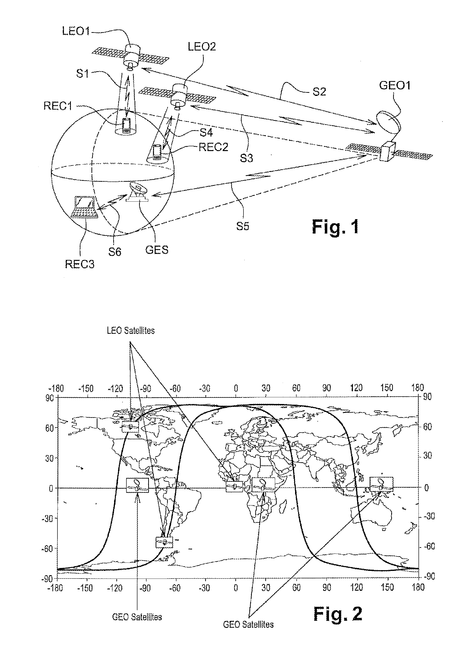
[0078]The architecture of the system is shown in FIGS. 1 and 2. As can be seen in these figures, the proposed system uses two satellite constellations. The first constellation is composed of one or more geostationary satellites (also called GEO in the remainder of the description).

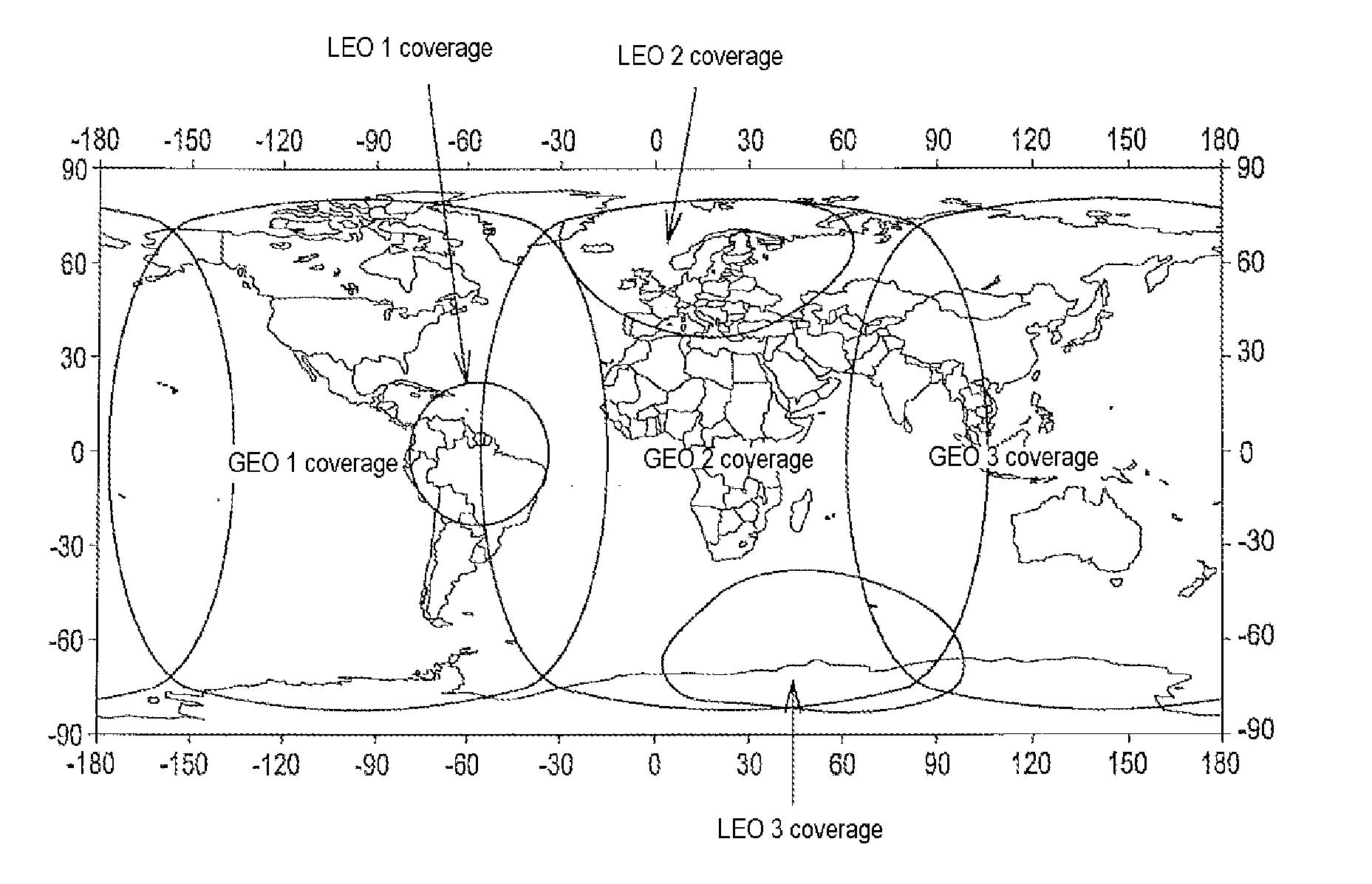
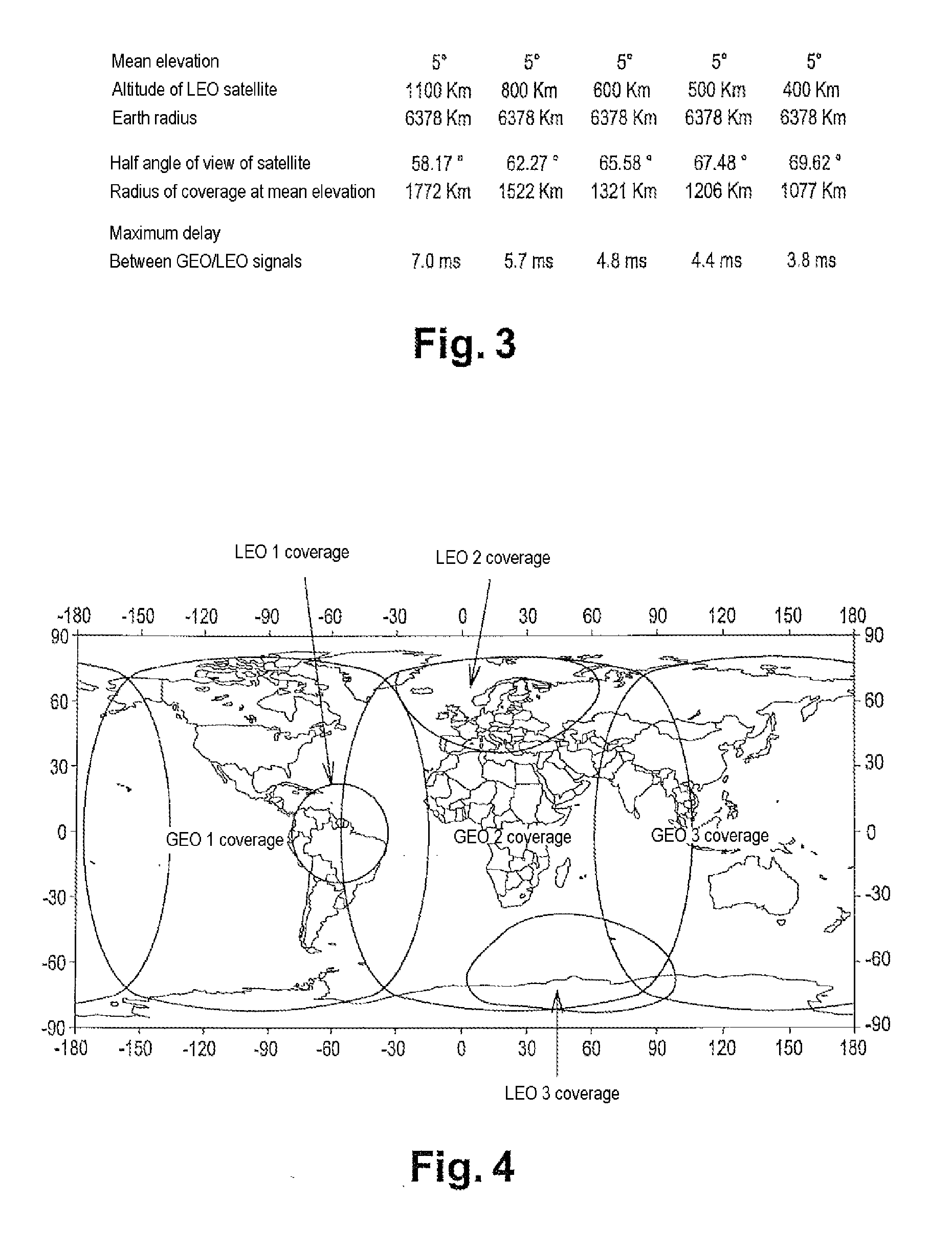
[0079]The system, described by way of an entirely non-limiting example, is based on a constellation of three geostationary satellites GEO1, GEO2, GEO3, placed in geostationary orbit above the three main continental areas (for example, at the longitudes of 265° E, 25° E, and 145° E respectively, as shown in FIG. 2). The geostationary satellites GEO1, GEO2, GEO3 operate in what is known as the MSS L-band (1.5 / 1.6 GHz).

[0080]The constellation of geostationary satellites GEO1, GEO2, GEO3 is tracked by one or more terrestrial tracking stations, positioned in view of the geostationary satellites GEO1, GEO2, GEO3 monitored by them, which perform tracking and remote control functions. The constellation of geostati...


PUM


Abstract

A telecommunications system for intermittent data transfer from and to at least one user located substantially on the surface of a celestial body. The system comprises at least one surface transmitter / receiver terminal associated with each user, one or more signal repeater means for the signals transmitted and / or received from the surface terminals. Each moving repeater means has at least one antenna oriented toward the surface of the celestial body, and adapted to allow communications from and to surface terminals. Each antenna produces a transmission / reception beam, the track of which on the surface of the celestial body forms the ground track, the progressive sweeping of the surface by this ground track forming a strip called a swath.

Description

TECHNICAL FIELD OF INVENTION[0001]The invention relates to the field of long-distance data transmission systems. More specifically, it relates to systems and methods for data communications (that is to say for data transfer, remote control, terminal monitoring, and the like) between users possessing small mobile terminals.BACKGROUND OF THE INVENTION AND PROBLEM POSED[0002]The problem of long-distance data transmission from or to a mobile terminal arises, in particular, in the case of links between computers (known as machine to machine links). This field of transmission is characterized by a data rate requirement which is markedly lower than that of image or Internet links, or alternatively by a capacity to use an intermittent link rather than a continuous one.[0003]In this case, the satellite serves as a communications link between the two parties, and the latency time of acknowledgements and messages is a function of the distance between the satellite and the ground station (also ...

Claims


Application Information

Patent Timeline
IPC IPC(8): H04B7/185
CPCH04B7/18519H04B7/18513H04B7/18521H04B7/18576
Inventor TRONC, JEROMEDUNAT, JEAN-CHRISTOPHE
Owner AIRBUS DEFENCE & SPACE
Why Eureka
Try Eureka