
Dry insertion and one-point in vivo calibration of an optical analyte sensor

a technology optical analyte, applied in the field of vivo calibration of optical analyte sensor, can solve the problems of increased complexity and potential uncertainty, time-consuming and time-consuming current sensor calibration, and increased patient discomfor

Active Publication Date: 2014-05-08
MEDTRONIC MIMIMED INC
View PDF4 Cites 10 Cited by
  • Summary
  • Abstract
  • Description
  • Claims
  • Application Information

AI Technical Summary

Benefits of technology

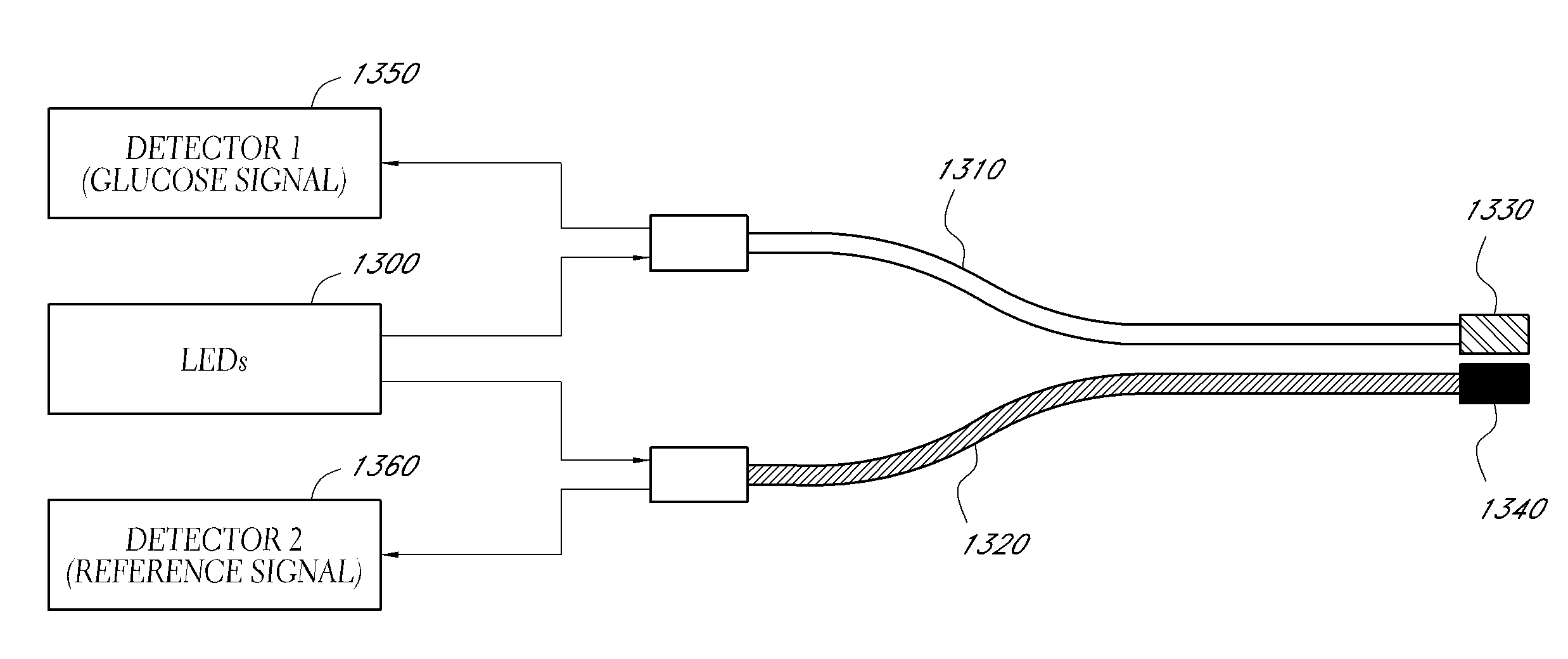
This patent describes a method and sensor for monitoring glucose concentration in a patient's body. The sensor involves a hydrogel containing a fluorescence chemical indicator system that is immobilized on the end of an optical fiber. The chemical indicator system is calibrated against an independently measured glucose concentration and pH levels in the patient's body. The sensor is then placed in the patient's body and the glucose concentration is monitored by detecting the fluorescence signal. The method and sensor provide a non-invasive and accurate way to measure glucose concentration in a patient's body.

Problems solved by technology

Current sensor calibration can be time-consuming, uncomfortable, and intrusive for a patient, requiring multiple blood draws or constant sampling for ex-vivo analysis of blood sugar concentration to compare to a signal comprising the output of the analyte sensor.
In cases where the sensor output is not linear when compared to the concentration of analyte, or only linear for a range of concentrations, additional complexity and potential uncertainty arises, requiring greater attention, more time, and more difficulty in performing a reliable calibration.
In some instances, such dilution can result in additional analyte being extracted from cells present in the blood sample, resulting in a change in the amount of analyte that would be reported by the different methods.
In some instances, problems can occur when measurements for a patient are made by one methodology, and the treatment protocol had been determined based on another methodology.
While providing for less discomfort to a patient, calibration outside of a patient's body may not be as accurate as calibration inside a patient's blood stream, where the sensor could take into account the physiological conditions of the patient.
Errors in calibration of analyte sensors can lead to erroneous measurements.
Reliance on such erroneous measurements, such as for medical treatment, or a mismatch between analytical technique and treatment protocol can lead to adverse responses and possibly life-threatening situations.

Method used


Image

  • Dry insertion and one-point in vivo calibration of an optical analyte sensor
  • Dry insertion and one-point in vivo calibration of an optical analyte sensor
  • Dry insertion and one-point in vivo calibration of an optical analyte sensor

Examples


Embodiment Construction

[0057]The following description and examples illustrate some embodiments of the disclosure in detail. Those of skill in the art will recognize that there are numerous variations and modifications of this disclosure that are encompassed by its scope. Accordingly, the description of a certain exemplary embodiment should not be deemed to limit the scope of the present disclosure.

[0058]Disclosed herein are methods of calibrating an analyte sensor capable of measuring the concentration of an analyte. The methods of calibrating can be used on various systems that are configured to measure the concentration of an analyte, such as a fluorescent based system, lifetime chemistry based system, electrochemical system, and other systems known in the art. In various embodiments, the calibration can be used with the sensor to determine the amount of analyte present, or the amount that another method or instrument would determine to be present, and in some embodiments to display the analyte concent...


PUM


Abstract

Disclosed are embodiments that relate to the deployment of a glucose sensor comprising an optical fiber into a physiological fluid, wherein the optical fiber has disposed along a distal region thereof a chemical indicator system comprising a fluorophore and a glucose binding moiety immobilized within a hydrogel, wherein the components of the chemical indicator system are in a dry state before deployment. Also disclosed is a one-point in vivo calibration of the chemical indicator system based on an independently measured glucose concentration.

Description

INCORPORATION BY REFERENCE TO ANY PRIORITY APPLICATIONS[0001]Any and all applications for which a foreign or domestic priority claim is identified in the Application Data Sheet as filed with the present application are hereby incorporated by reference under 37 CFR 1.57.BACKGROUND[0002]1. Field[0003]Disclosed herein are methods and algorithms for calibrating an optical analyte sensor in vivo.[0004]2. Description of the Related Art[0005]Analyte sensors, such as glucose sensors, for detecting and measuring the presence of different chemical species in samples are well known. To assure analyte measurement accuracy, whether as a gauge of the amount of analyte present or to agree with a measurement made by another instrument, an analyte sensor generally requires calibration. Such calibration is frequently necessary to account for sensor-to-sensor variation and for differences in the environment where the sensor will be placed.[0006]Current sensor calibration can be time-consuming, uncomfo...

Claims


Application Information

Patent Timeline
Patent Type & Authority Applications(United States)
IPC IPC(8): A61B5/145A61B5/1455
CPCA61B5/14532A61B5/1455A61B5/14539A61B5/1459A61B5/14735A61B5/1495A61B2562/043A61B2562/223
Inventor GALLANT, STUART L.MARKLE, WILLIAM H.GOHARLA'EE, MANO
Owner MEDTRONIC MIMIMED INC
Learn More