Foley catheter

a catheter and temperature sensor technology, applied in the field of improved catheters, can solve the problems of urethral abrasion, difficult removal of catheters, irregularities and bumps of the surface of the catheter, etc., and achieve the effect of easy slid

Inactive Publication Date: 2014-05-08
BERAN ANTHONY V
View PDF6 Cites 25 Cited by
  • Summary
  • Abstract
  • Description
  • Claims
  • Application Information

AI Technical Summary

Benefits of technology

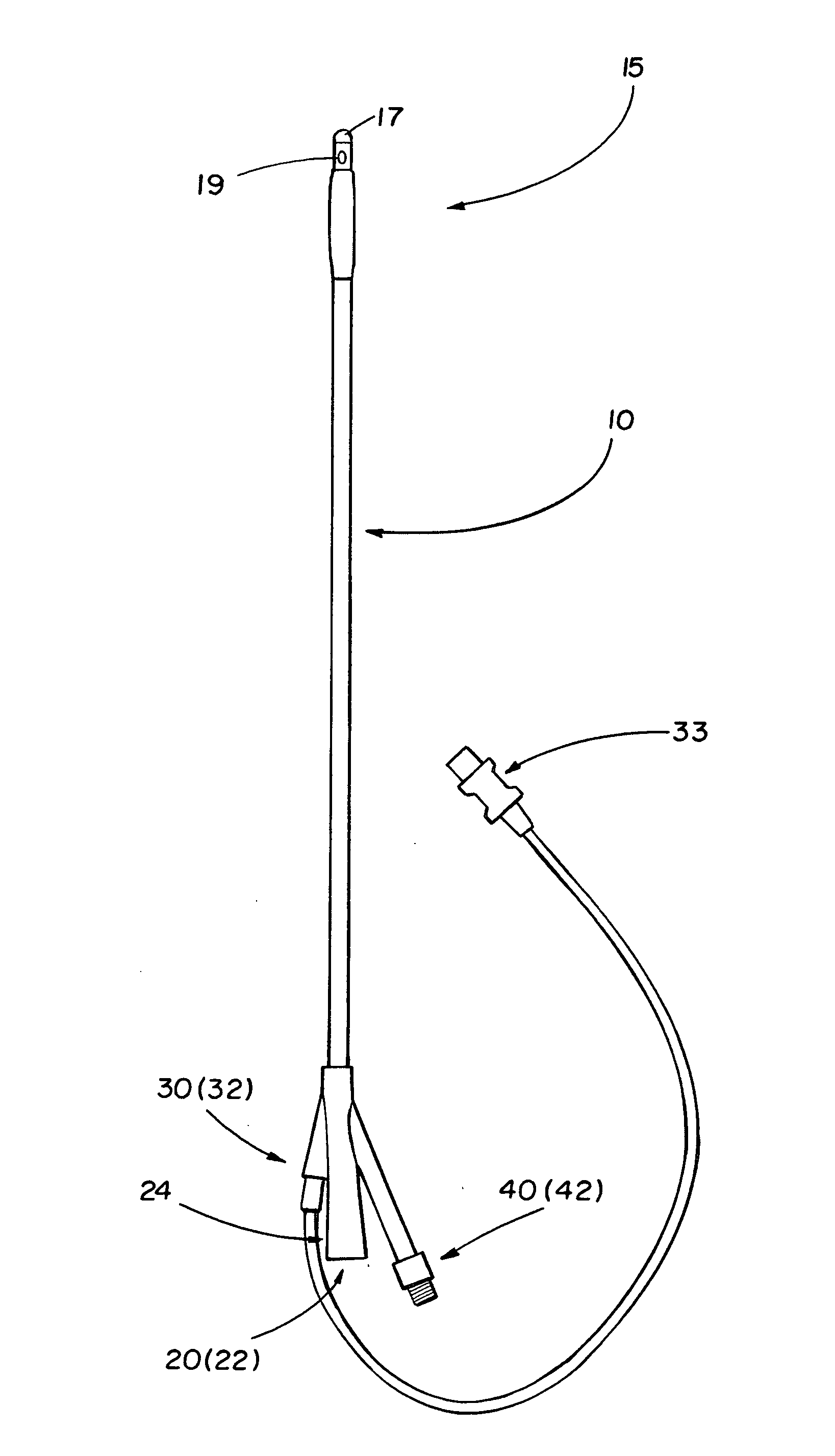
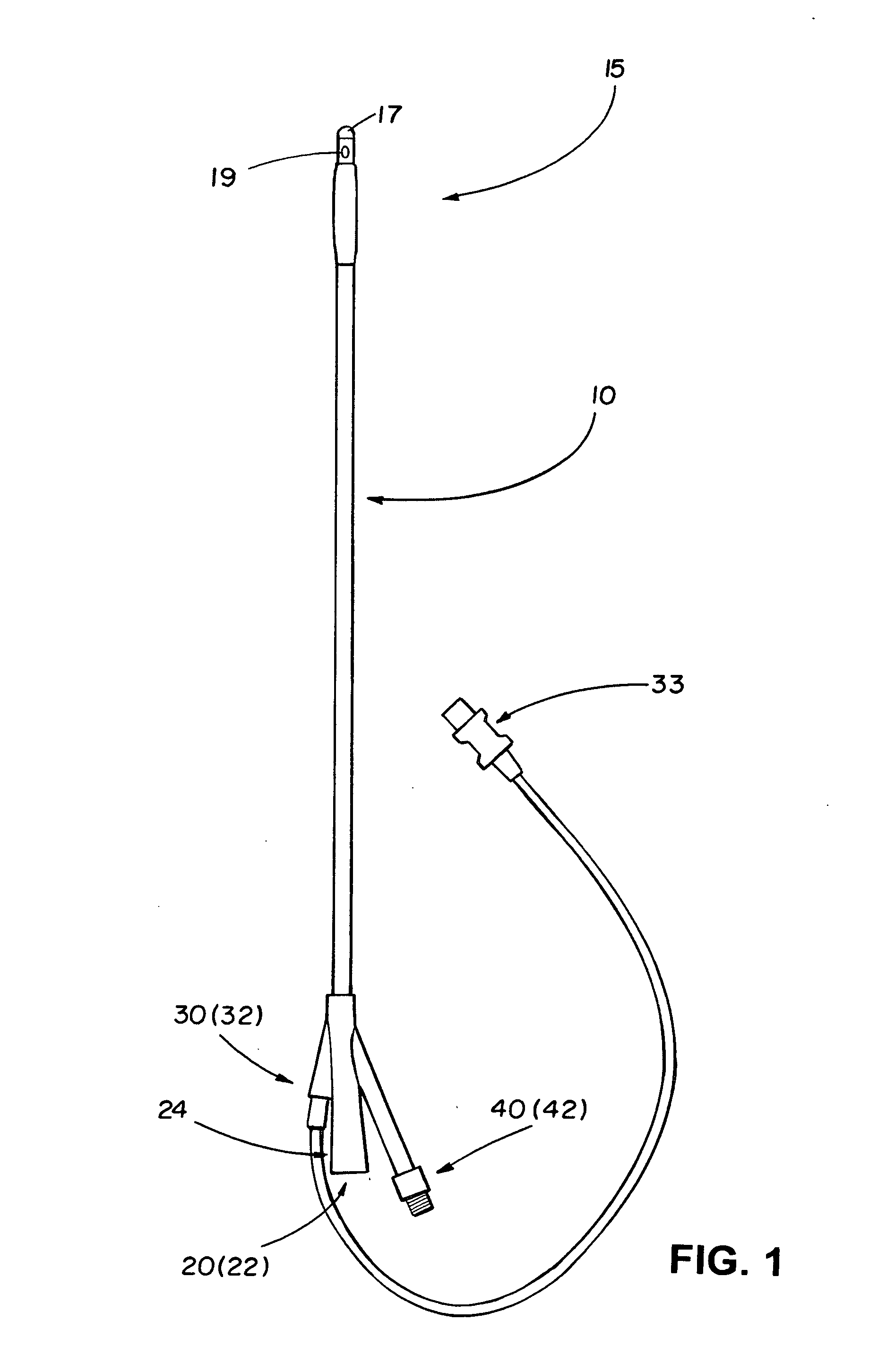
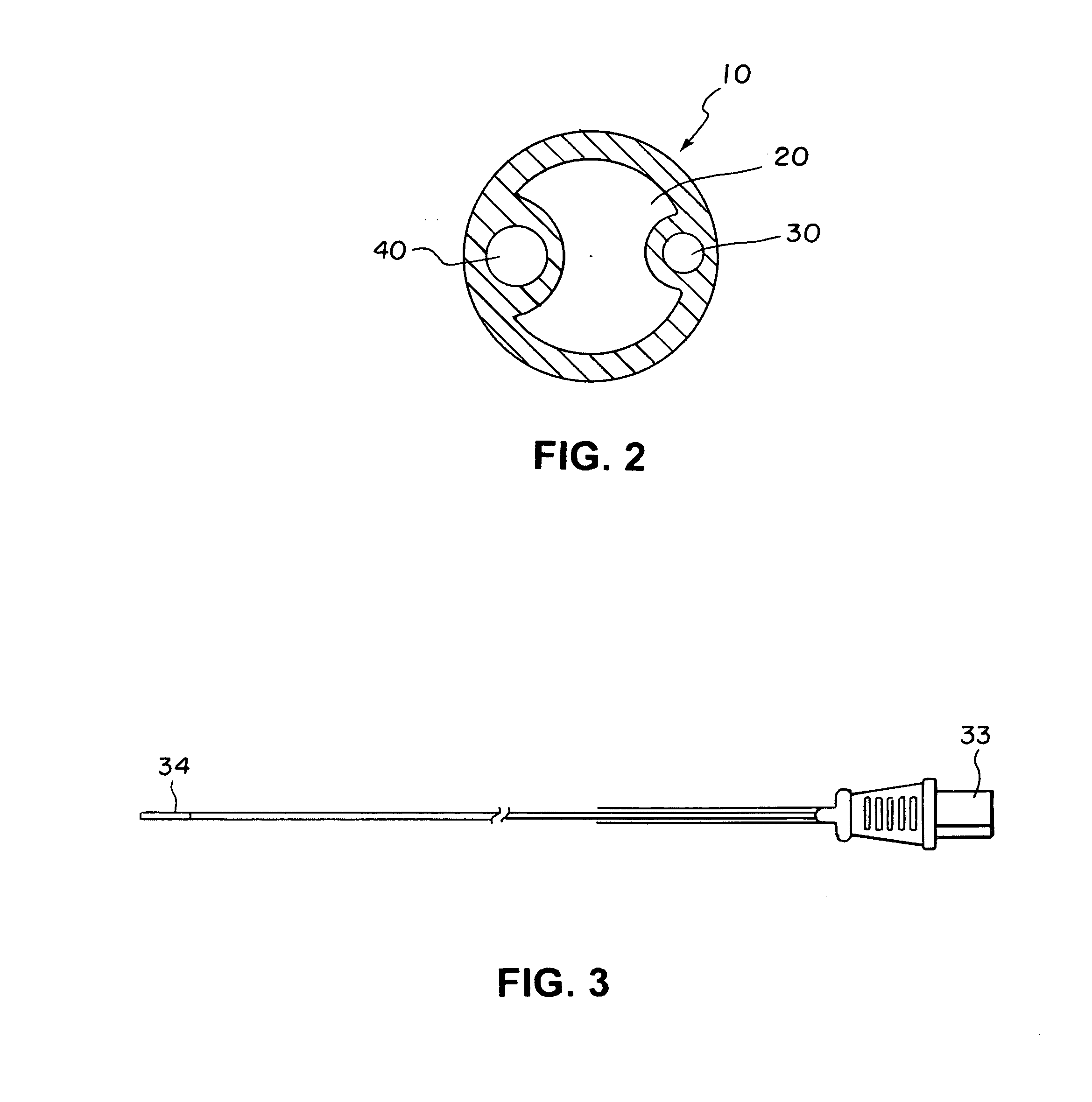
[0005]The present invention is an improved catheter, in particular, a Foley catheter. The preferred embodiment of the invention is a catheter with three lumens. The largest lumen is the drainage lumen. The side balloon lumen has a removable one-way female Luer valve threaded onto the distal end of the side balloon lumen. The removable Luer valve allows a user to drain the balloon by passive equilibrium to atmospheric pressure by removing the valve from the lumen. Alternately, the lumen can be drained by syringe. The temperature sensor lumen contains a sensor lead with a Teflon(R) outside jacket that allows the lead to more easily slide within the lumen when the lumen is stretched or retracts. The sensor lead is also preferably fixed only to the distal end of the lumen so the lead will not stretch with the lumen, but would move freely within the lumen.

Problems solved by technology

The prior art Foley catheters with temperature sensors can develop irregularities and bumps on the surface of the catheter as the catheter is removed from a patient.
The irregularities and bumps caused by this uneven response to a pull on the catheter can make removal of the catheter more difficult and can cause urethral abrasion.
Another issue with prior art Foley catheters is the removal of the sterile water from the catheter retention balloon without creating creases on the surface of the balloon and without leaving water inside the balloon.
Either condition can result in difficult catheter withdrawal and possible urethral injury.
However, the uncontrolled application of negative pressure can result in fluid retention within the balloon if insufficient pressure is applied or crease on the balloon's surface when excessive pressure is applied.

Method used


Image

  • Foley catheter
  • Foley catheter
  • Foley catheter

Examples


Embodiment Construction

[0017]Various embodiments are now described with reference to the drawings, wherein like reference numerals are used to refer to like elements throughout. In the following description, for purposes of explanation, numerous specific details are set forth in order to provide a thorough understanding of one or more embodiments. It may be evident, however, that such embodiment(s) may be practiced without these specific details.

[0018]In the following paragraphs, the present invention will be described in detail by way of example with reference to the attached drawings. Throughout this description, the preferred embodiment and examples shown should be considered as exemplars, rather than as limitations on the present invention. As used herein, the “present invention” refers to any one of the embodiments of the invention described herein, and any equivalents. Furthermore, reference to various feature(s) of the “present invention” throughout this document does not mean that all claimed embo...


PUM


Abstract

The present invention is an improved catheter, in particular, a Foley catheter. The preferred embodiment of the invention is a catheter with three lumens. The largest lumen is the drainage lumen. The side balloon lumen has a removable one-way female Luer valve threaded onto the distal end of the side balloon lumen. The removable Luer valve allows a user to drain the balloon by passive equilibrium to atmospheric pressure by removing the valve from the lumen. Alternately, the lumen can be drained by syringe. The temperature sensor lumen contains a sensor lead with a Teflon(R) outside jacket that allows the lead to more easily slide within the lumen when the lumen is stretched or retracts. The sensor lead is also preferably fixed only to the distal end of the lumen so the lead will not stretch with the lumen, but would move freely within the lumen.

Description

TECHNICAL FIELD[0001]The present invention is an improved catheter, in particular, a Foley catheter.BACKGROUND ART[0002]A Foley catheter is a flexible tube that is usually passed through the urethra and into the bladder. The tube has two or more separated channels, or lumens, running down its length. One lumen is open at both ends, and allows urine to drain out into a collection bag. Another lumen, or side lumen, typically has a valve on the outside end and connects to a balloon at the tip; the balloon is inflated with sterile water when it lies inside the bladder, in order to stop it from slipping out. Foley catheters are commonly made from silicone rubber or natural rubber. A temperature, or thermistor, sensor can be placed inside one of the Foley catheter's side lumen with a sensing tip positioned at the catheter's proximal end. The proximal end is usually beveled for atraumatic insertion. The temperature sensor is used to measure a patient's bladder or core temperature.[0003]The...

Claims


Application Information

Patent Timeline
Patent Type & Authority Applications(United States)
IPC IPC(8): A61M25/00A61B5/01
CPCA61B5/01A61M25/0017
Inventor BERAN, ANTHONY V.
Owner BERAN ANTHONY V
Why Eureka
Try Eureka