Method and apparatus for camera-based 3D flaw tracking system

Inactive Publication Date: 2014-05-15
CYBERNET SYST
View PDF21 Cites 32 Cited by
  • Summary
  • Abstract
  • Description
  • Claims
  • Application Information

AI Technical Summary

Problems solved by technology

It is sometimes necessary to precisely measure large structures to verify dimensions and, in some case, precisely locate flaws.

Method used


Image

  • Method and apparatus for camera-based 3D flaw tracking system
  • Method and apparatus for camera-based 3D flaw tracking system
  • Method and apparatus for camera-based 3D flaw tracking system

Examples


Embodiment Construction

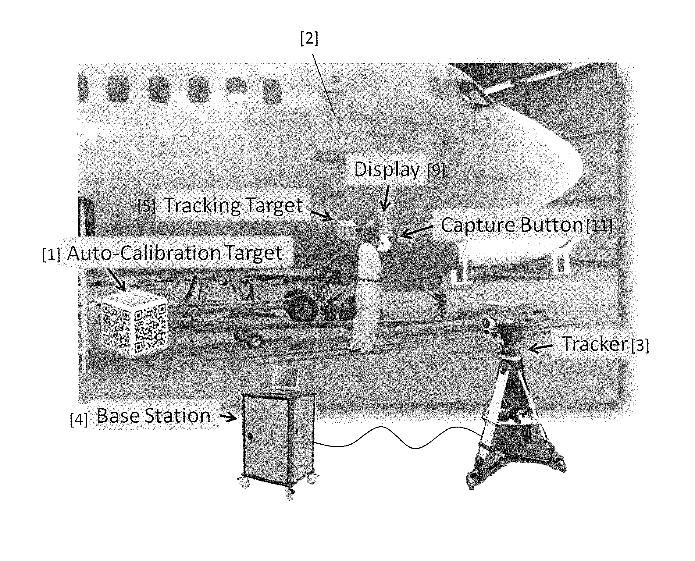
[0015]The present invention is directed to methods and apparatus for generalized 3D tracking of fiducials with the automatic mapping of flaw data to component models within standard CAD packages. The methods and apparatus of the invention are suitable for many various tracking applications, and particularly well-suited to large inspection sites which require vast coverage with a medium-degree of accuracy. The system provides at least the following capabilities:[0016]1. Automatically tracks a fiducial attached to a sensor with minimal requirements from the user;[0017]2. Maps the location data and associated sensor data into a computer-aided design (CAD) model;[0018]3. Automatically calibrates itself;[0019]4. Gives quarter-inch accuracy 3D position & pose; and[0020]5. Puts the location and sensor data into a database;

[0021]A primary goal of the system it to repeatably re-find flaws over the surface of a large object like an aircraft in multiple measurement sessions, perhaps spaced in ...


PUM

PropertyMeasurementUnit
heightaaaaaaaaaa
surface inspectionaaaaaaaaaa
fields of viewaaaaaaaaaa

Abstract

Systems and methods facilitate long-range, accurate fiducial tracking using a mixture of pan-tilt and camera devices enabling generalized 3D tracking of fiducials with the automatic mapping of flaw data to component models within standard CAD packages. The invention is suitable to many various tracking applications, particularly large inspection sites such as aircraft surfaces which require vast coverage with a medium-degree of accuracy. A method of surface inspection comprises the steps of moving a fiducial target over a surface under inspection, and tracking the fiducial as it is moved by capturing and storing the coordinates of the fiducial in a database for subsequent retrieval. Machine vision is used to acquire surface inspection data associated with the coordinates of the fiducial as it is moved. The inspection data is integrated into a CAD model, enabling the use of finite element analysis (FEA) to determine or predict flaw and material behavior over time.

Description

REFERENCE TO RELATED APPLICATION[0001]This application claims priority from U.S. Provisional Patent Application Ser. No. 61 / 726,942, filed Nov. 15, 2012, the entire content of which is incorporated herein by reference.FIELD OF INVENTION[0002]The present invention relates generally to systems and methods for tracking and mapping of flaws, and more particularly to systems and methods for long-range, accurate fiducial tracking using a mixture of pan-tilt and camera devices.BACKGROUND OF THE INVENTION[0003]It is sometimes necessary to precisely measure large structures to verify dimensions and, in some case, precisely locate flaws. Many alternative means for accomplishing this include using laser range finding [Ohtomo et al., Ohishi et al., Kumagi et al., Medina, and SICK], theodolite survey equipment [Gotoh, Benz et al., Leica], laser triangulation [Ura, Kaneko, Sasaki et al., Bosch], autofocus controls [Tsuda et al.] and 3D computer vision (which uses relative object sizes, stereopsis...

Claims


Application Information

Patent Timeline
Patent Type & Authority Applications(United States)
IPC IPC(8): G01N21/88G06T7/00G06F17/50H04N13/02
CPCG01N21/8806H04N13/0221G06T7/0004G06F17/50G01N21/9515G06T7/001G06T2207/10016G06T2207/30164G06T2207/30208G06F30/00
Inventor FOULK, EUGENETANG, KEVINBEACH, GLENN J.
Owner CYBERNET SYST
Why Eureka
Try Eureka