Image processing apparatus, method of controlling the same, and storage medium

a technology of image processing and storage media, which is applied in the field of image processing apparatus, a method of controlling the same, and a storage medium, and can solve the problems of increasing the size of the electric circuit, increasing the cost and electric power consumption, and affecting performan

Inactive Publication Date: 2014-05-15
CANON KK
View PDF5 Cites 0 Cited by
  • Summary
  • Abstract
  • Description
  • Claims
  • Application Information

AI Technical Summary

Benefits of technology

[0012]An aspect of the present invention is to eliminate th

Problems solved by technology

Specifically, a problem was occurring in that, as shown in FIG. 2, when a straight line is printed in a main scanning direction, toner would scatter backwards from a line 202 printed on a sheet 201 with respect to a conveyance direction of a sheet and spoil the image.
Because, in a case where the aforementioned adjustment processing of toner application amount is performed in hardware, a reference window for acquiring vicinity pixel information is set, and SRAM is used as a line buffer for the window, there exists a problem in that the scale of the electric cir

Method used


Image

  • Image processing apparatus, method of controlling the same, and storage medium
  • Image processing apparatus, method of controlling the same, and storage medium
  • Image processing apparatus, method of controlling the same, and storage medium

Examples


second embodiment

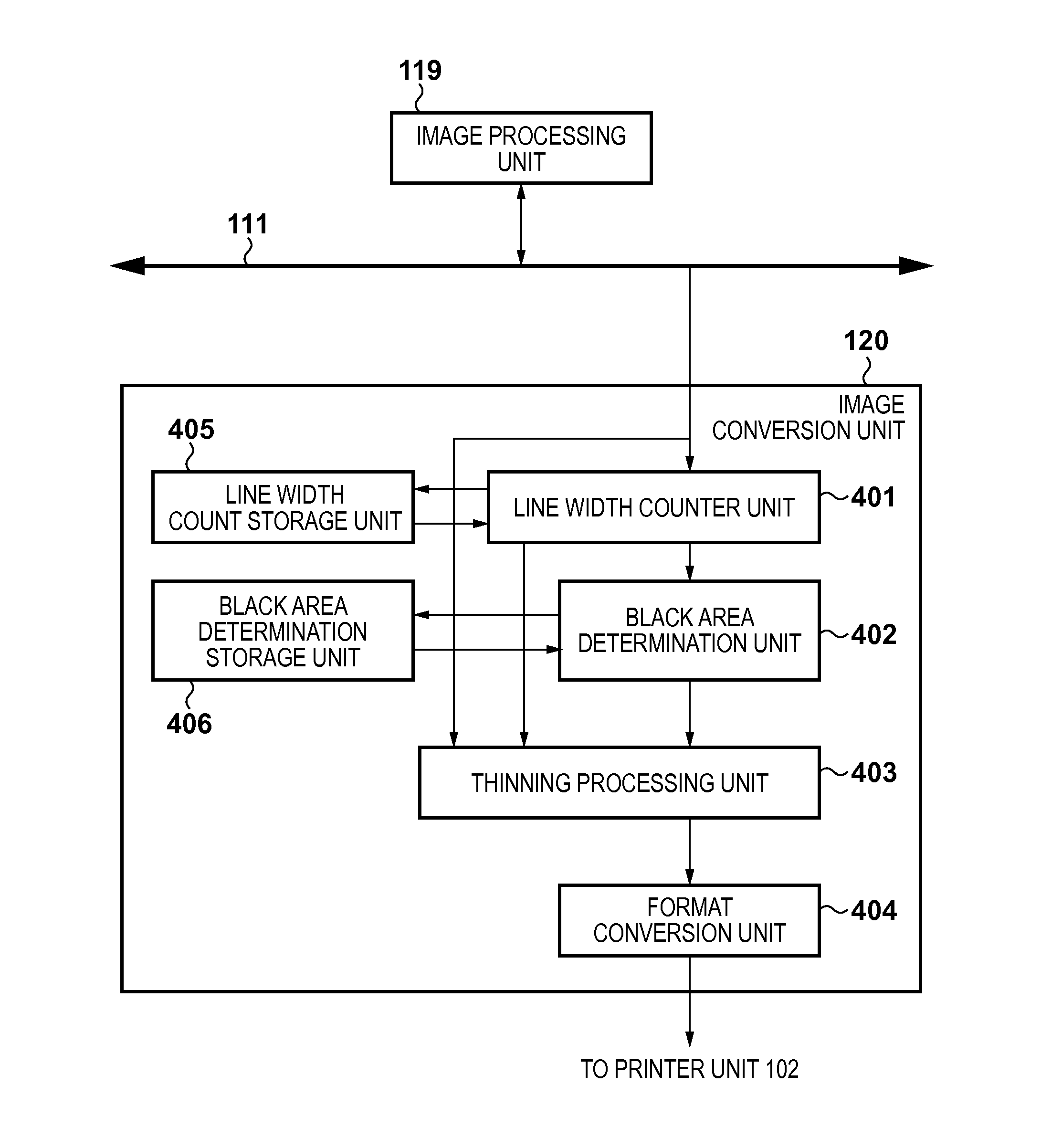
[0080]In the second embodiment, explanation will be given for a case where a thinning processing method different from that used in the previously described first embodiment is used.

[0081]In the previously described first embodiment, the line widths are determined from the line counter values obtained from the line width counter unit 401, and thinning processing is performed by the thinning processing unit 403 in accordance with the line widths. In contrast to this, in the second embodiment, processing is performed for changing the sub-scanning direction upstream area line counter maximum value by changing the size of the reference window in accordance with apparatus characteristics.

[0082]The thinning characteristic is that the line width at which the tailing blur occurs differs according to the image forming speed of the image forming apparatus. Accordingly, when the size of the reference window changes, it is necessary to change the consecutive line number counter value. In other ...

third embodiment

[0084]In the previously described first embodiment, the line width is determined from the line counter values obtained from the line width counter unit 401, and thinning processing is performed by the thinning processing unit 403 in accordance with the line width. In the third embodiment, processing for changing the upstream area line counter maximum value is performed by changing the reference window size in accordance with apparatus characteristics. The thinning characteristic is that the line width at which the tailing blur occurs differs in accordance with a resolution of the image forming apparatus. However, because the physical line width at which the tailing blur occurs does not change, for example, in a case where image data having a resolution of 1200 dpi is processed, the line width is twice what it is when the resolution is 600 dpi. For example, in a case where the resolution is 600 dpi, the window size is made to be 16 lines, and when it is 1200 dpi, the window size is m...

fourth embodiment

[0086]In the previously described first embodiment, the line width is determined from a line counter value obtained from the line width counter unit 401, and thinning processing is performed by the thinning processing unit 403 in accordance with the line width. In contrast to this, in the fourth embodiment, processing is performed for changing the sub-scanning direction upstream area line counter maximum value by changing the size of the reference window in accordance with apparatus characteristics. The thinning characteristic is that the line width at which the tailing blur occurs differs in accordance with a humidity level of the surrounding environment of the image forming apparatus. Accordingly, it is determined how easily the tailing blur can occur by estimating an amount of moisture contained from a humidity level and temperature, and, for example, use a larger line width in a case of high temperature and humidity (for example 16 lines) and use a smaller line width in a case o...


PUM


Abstract

An image processing apparatus, an image processing method for controlling it, and a storage medium. The image processing apparatus determines whether or not a line of interest is a black line, and counts, when it is determined that the line of interest is the black line, the number of consecutive black lines. It determines whether or not the line of interest is in a black area in accordance with whether or not the number of consecutive black lines counted in the counting is greater than a predetermined value, and in a case that it is determined that the line of interest is the black line and it is determined that the line of interest is not in the black area, it executes thinning processing for the line of interest.

Description

BACKGROUND OF THE INVENTION[0001]1. Field of the Invention[0002]The present invention relates to an image processing apparatus, a method of controlling the same, and a storage medium.[0003]2. Description of the Related Art[0004]Amongst image processing apparatuses having a print function, printing of data generated by a computer or the like has become more common. Image processing apparatuses such as laser beam printers receive commands and coded text and graphical information related to printing from a host computer such as a computer or a workstation. The received command information is converted into pixel information by rendering means, and based on image signals generated based on this pixel information an image is formed (printed).[0005]In this image forming, adjustment processing of detecting black lines and adjusting a toner application amount may be performed. This processing is for preventing an occurrence of such things as toner scattering when, upon developing, an amount...

Claims


Application Information

Patent Timeline
IPC IPC(8): G06K15/02G06K15/12
CPCG06K15/12G06K15/1869G06K15/1871
Inventor NOMURA, YOSHIHISA
Owner CANON KK
Why Eureka
Try Eureka