Posterior spinal prosthesis

a spinal prosthesis and posterior spine technology, applied in the field of spinal prosthesis, can solve the problems of insufficient to address the overexposure of the vulnerable spinal cord, and the potential for and other known spinal devices also do not address these problems. , to achieve the effect of preventing post-operative soft tissue cavitation

Active Publication Date: 2014-05-15
LIFE SPINE INC
View PDF3 Cites 25 Cited by
  • Summary
  • Abstract
  • Description
  • Claims
  • Application Information

AI Technical Summary

Benefits of technology

The present posterior spinal prosthesis provides coverage of the exposed spinal cord, soft tissue, and / or adipose tissue, which are commonly removed during spinal decompression procedures. It also provides stability to the associated vertebrae and helps prevent post-operative soft tissue cavitation. The prosthesis helps to preserve the cervical, thoracic, and lumbar regions of the spine, providing anatomically accurate coverage and stability.

Problems solved by technology

There are various medical spinal procedures where cross-connectors or current spinal prostheses of any kind do not address all of the issues created by the various medical spinal procedures.
This procedure, however, can contribute to overexposure of the vulnerable spinal cord as well as create the potential for post operative soft tissue cavitation.
While current cross-connectors may be used for stabilization of the spinal fixation assemblies (and thus the affected vertebrae), they are not adequate to address overexposure of the vulnerable spinal cord or the potential for post operative soft tissue cavitation as a result of a spinal decompression procedure.
Other known spinal devices also do not address these problems.
Moreover, other medical spinal procedures may overexpose portions of the spinal cord or spinal cord area as well as create the potential for post operative soft tissue cavitation of which the known spinal devices do not address.

Method used


Image

  • Posterior spinal prosthesis
  • Posterior spinal prosthesis
  • Posterior spinal prosthesis

Examples


Embodiment Construction

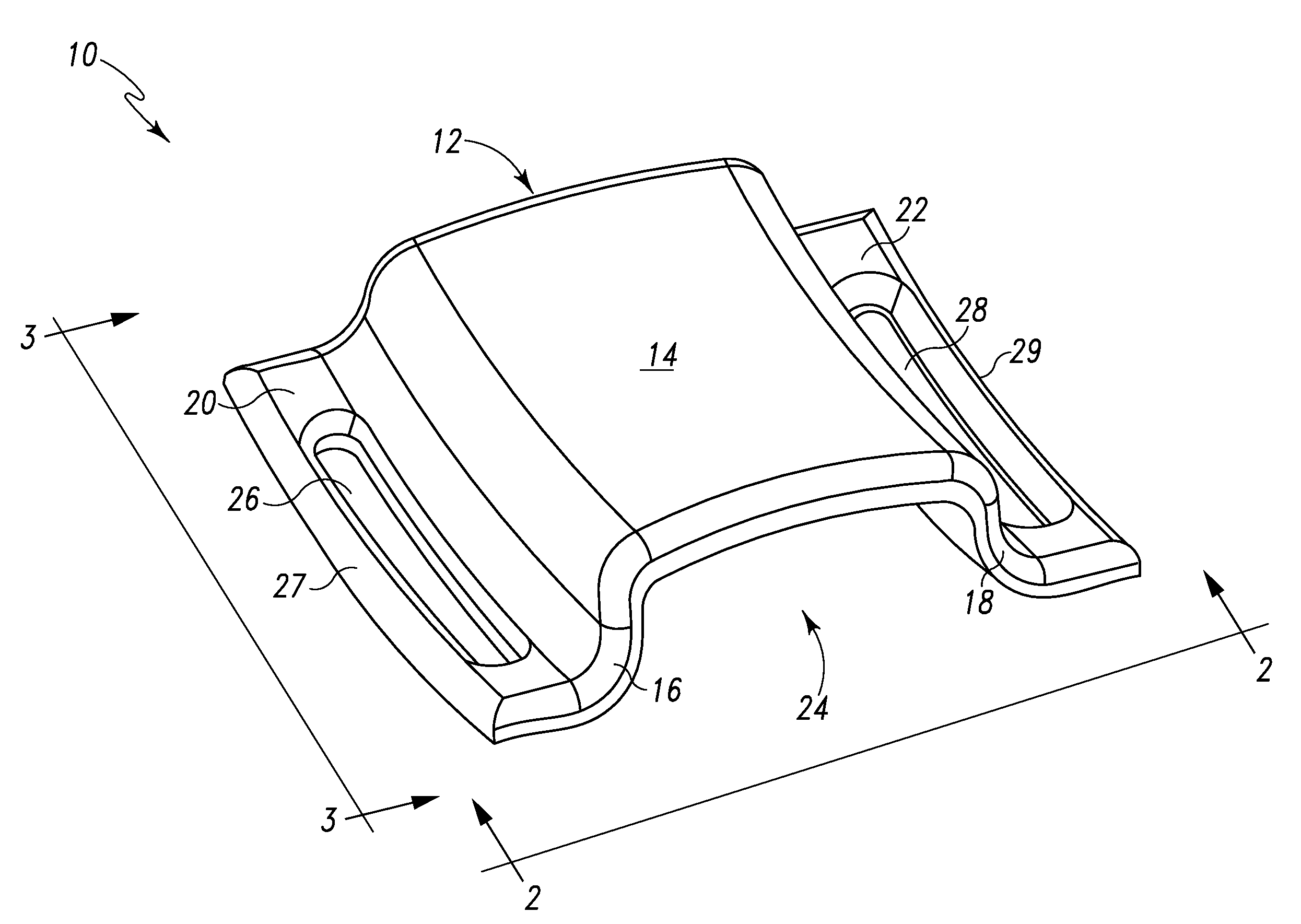
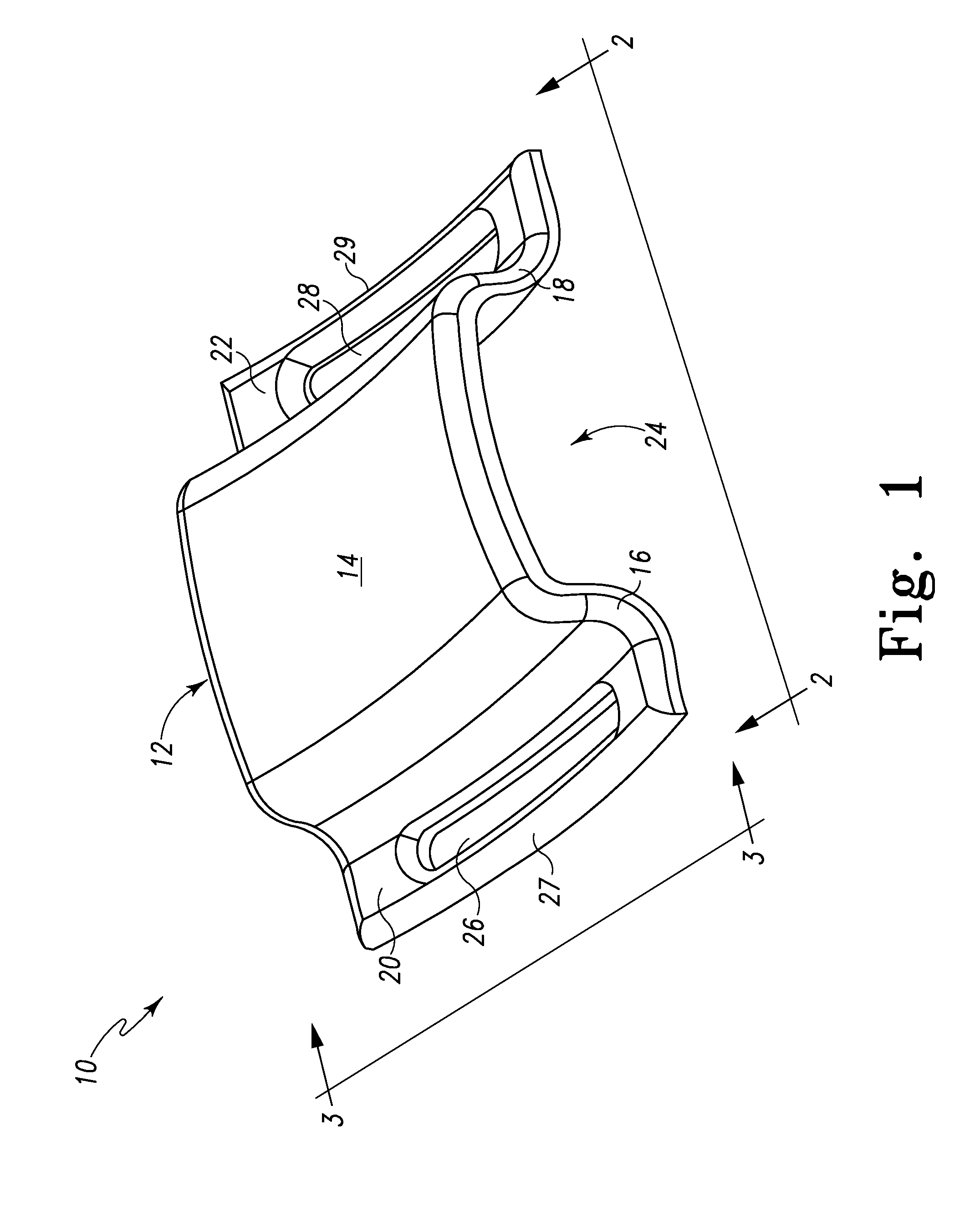
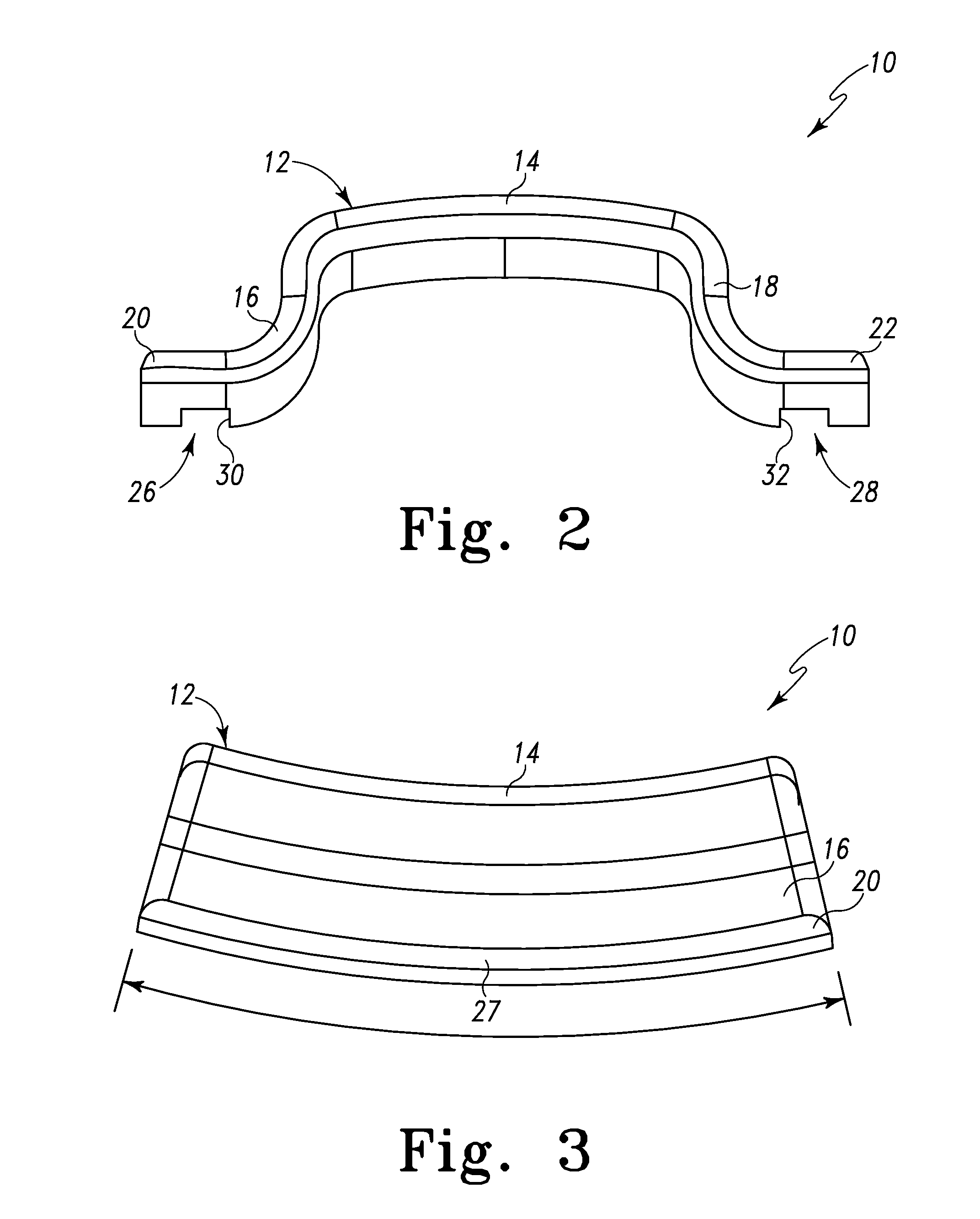
[0030]Referring to FIGS. 1-3 there is depicted an exemplary embodiment of a posterior spinal prosthesis, generally designated 10, fashioned in accordance with the present principles. It should be appreciated that the present posterior spinal prosthesis may be used for any portion of the spine such as on the cervical vertebrae, the thoracic vertebrae and / or the lumbar vertebrae. However, the present posterior spinal prosthesis is shown and described with reference to the cervical vertebrae. The present spinal prosthesis 10 is adapted to provide posterior coverage of an exposed spinal cord, soft tissue, Foramen and / or adipose tissue, of one or more vertebrae as a result of the removal the spinous processes and / or the spinous process and laminar hoods from one or more vertebrae of the spine such as for a spinal decompression procedure. The posterior spinal prosthesis also provides posterior stabilization of the associated vertebrae as well as aiding in preventing post operative soft ti...


PUM


Abstract

A posterior spinal prosthesis is configured to cover exposed portions of a spinal column especially, but not necessarily, as a result of a medical spinal procedure and particularly, to provide posterior coverage of an exposed spinal cord, soft tissue, Foramen and / or adipose tissue, associated with one or more vertebrae as a result of the removal the spinous processes and / or the spinous process and laminar hoods from the one or more vertebrae of the spine as a result of a spinal decompression procedure or other reason. A plate forming the prosthesis is connectable to spine rod constructs implanted on lateral sides of the vertebrae and projects in the posterior direction relative to the connection. The plate is generally curved in the superior / inferior direction to provide either a lordotic or kyphotic curvature depending on the portion of the spine to which the prosthesis is utilized. As such, the posterior spinal prosthesis may be used on any portion of the spine such as the cervical vertebrae, the thoracic vertebrae and / or the lumbar vertebrae. The present posterior spinal prosthesis also provides posterior stabilization of the associated vertebrae as well as aiding in preventing post operative soft tissue cavitation at the decompression site.

Description

RELATED APPLICATIONS[0001]This patent application is a continuation of U.S. patent application Ser. No. 12 / 492,668 filed on Jun. 26, 2009, which claims the benefit of and / or priority to U.S. Provisional Patent Application No. 61 / 076,284 filed on Jun. 27, 2008, each of which are hereby incorporated herein by reference in their entireties.BACKGROUND OF THE INVENTION[0002]1. Field of the Invention[0003]The present invention relates to spinal devices and, in particular, to spinal prostheses for use with spinal fixation devices, assemblies and systems such as spinal screw and rod assemblies or systems that are attached onto a patient's spine.[0004]2. Background Information[0005]There are many medical situations, because of disease, injury or deformity, where it is necessary to align, hold and / or fix a desired relationship between adjacent vertebral bodies. In order to accomplish this goal, orthopedic spinal surgeons utilize spinal fixation devices, systems and / or assemblies to provide th...

Claims


Application Information

Patent Timeline
Patent Type & Authority Applications(United States)
IPC IPC(8): A61B17/70
CPCA61B17/7058A61B17/7032
Inventor BUTLER, MICHAEL S.PREDICK, DANIEL
Owner LIFE SPINE INC
Why Eureka
Try Eureka