
Gear assembly and electronic device using the same

a technology of electronic devices and gear assemblies, applied in the direction of gearing, clutches, freewheel clutches, etc., can solve problems such as paper jams or even operation errors, and achieve the effect of compact gear assembly siz

Inactive Publication Date: 2014-05-22
CAL COMP PRECISION SINGAPORE +1
View PDF0 Cites 1 Cited by
  • Summary
  • Abstract
  • Description
  • Claims
  • Application Information

AI Technical Summary

Benefits of technology

The present invention provides a gear assembly that can only be driven by the driving gear when it rotates at a certain speed, which prevents the driven gear from being accidentally driven and causing operational errors or paper jams. Additionally, an elastic member is placed in the driving gear to keep it in its original position when the driven gear is not being driven, which ensures that the gear assembly remains compact and does not increase in size. This invention not only prevents operational errors and paper jams, but also maintains the compact size of the gear assembly and the electronic device it is used with.

Problems solved by technology

Thus, the motor may accidentally drive the pick roller to rotate during the operation period which causes paper jam or even operation error.

Method used


Image

  • Gear assembly and electronic device using the same
  • Gear assembly and electronic device using the same
  • Gear assembly and electronic device using the same

Examples


Embodiment Construction

[0028]Reference will now be made in detail to the present preferred embodiments of the invention, examples of which are illustrated in the accompanying drawings. Wherever possible, the same reference numbers are used in the drawings and the description to refer to the same or like parts.

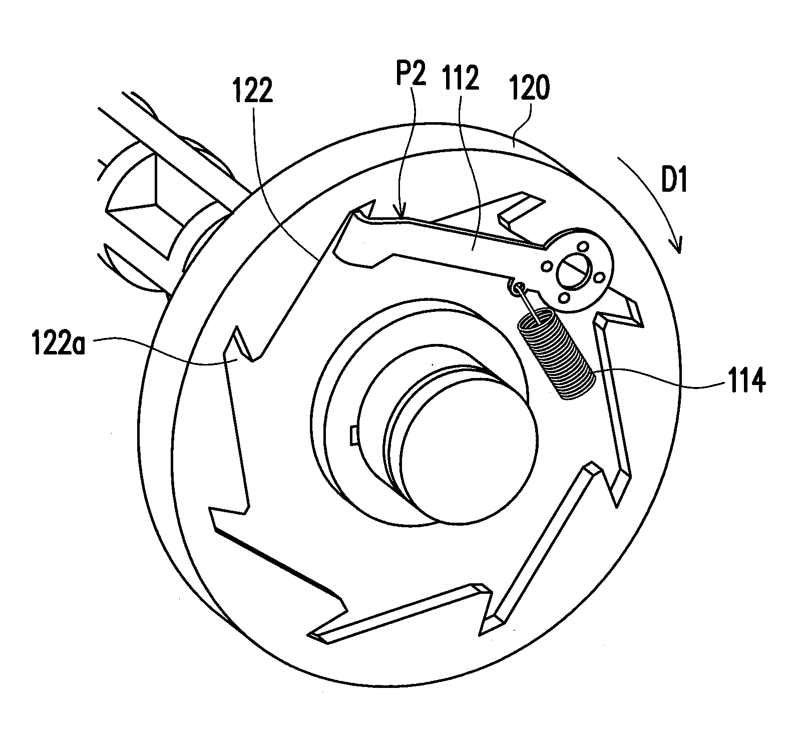
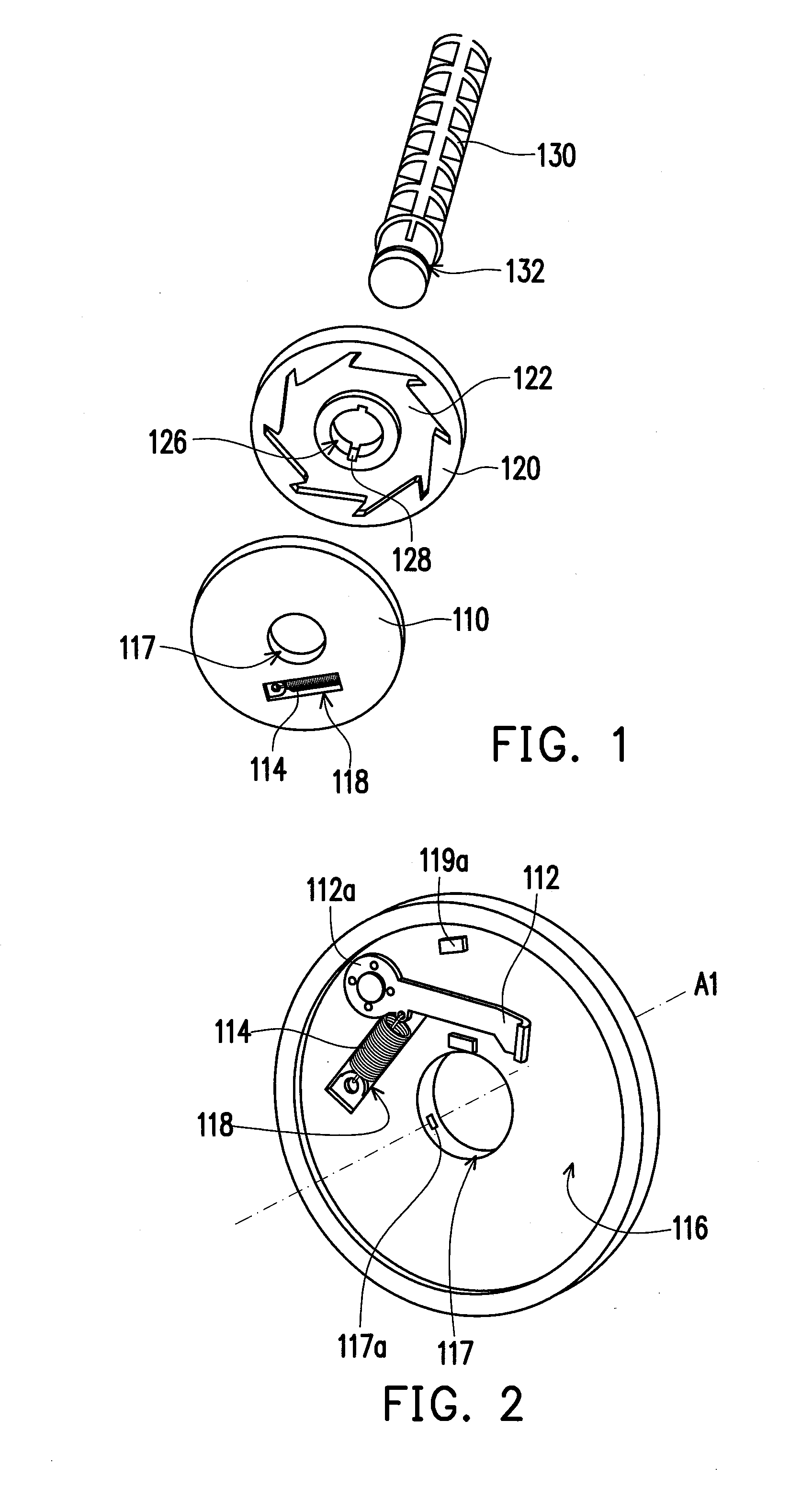
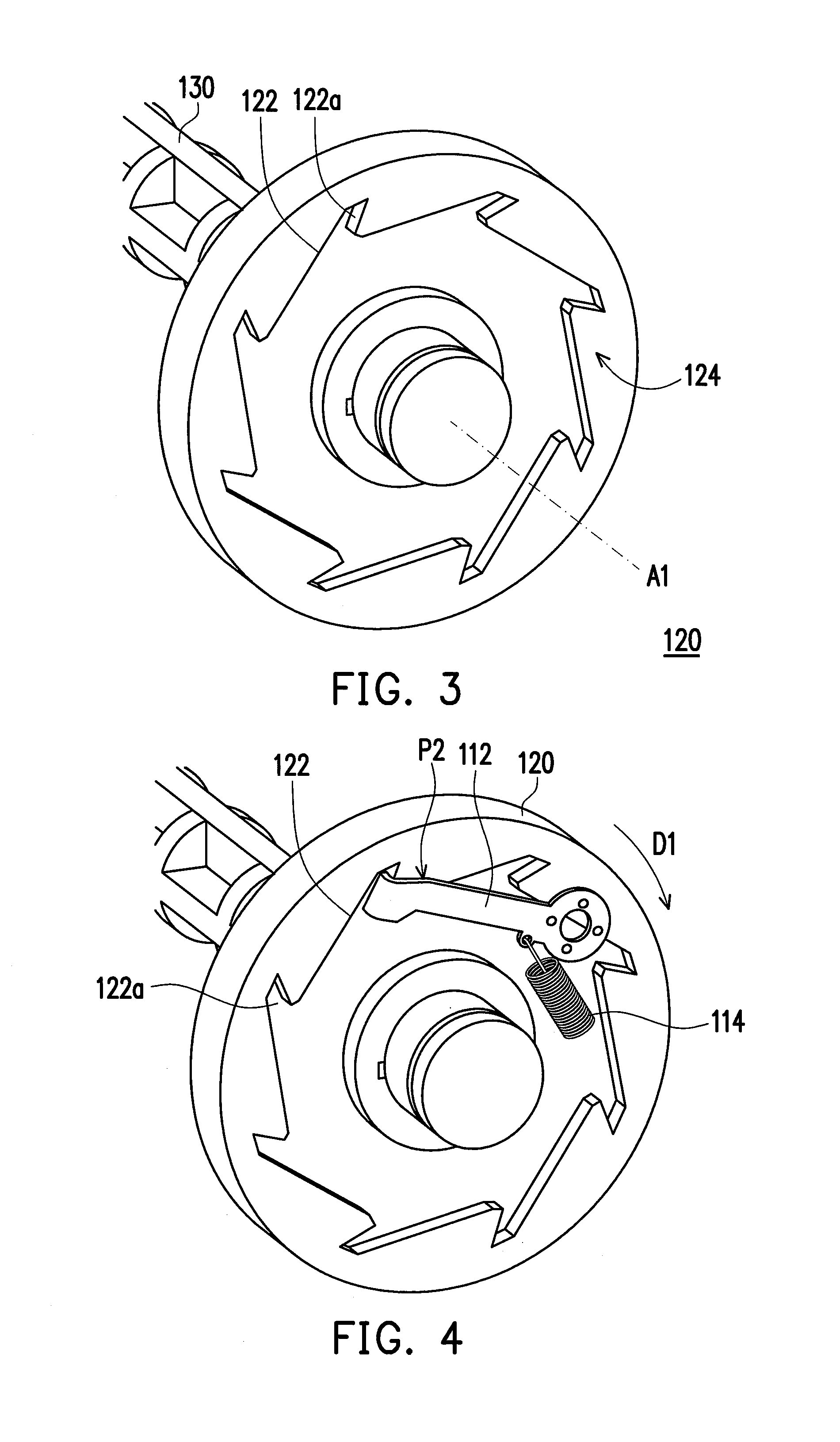
[0029]FIG. 1 is an exploded view of a gear assembly according to an embodiment of the invention. FIG. 2 is a schematic view of the driving gear of FIG. 1. FIG. 3 is a schematic view of the driven gear of FIG. 1. Please refer to FIG. 1 to FIG. 3, the gear assembly 100 of the present embodiment includes a driving gear 110 and a driven gear 120. The driving gear 110 is adapted to rotate about an axis A1. The driving gear 110 includes at least one pawl 112 (one is illustrated herein) and at least one elastic member 114. The pawl 112 is pivoted on a first surface 116 of the driving gear 110 so the pawl 112 is adapted to rotate about a pivoted point 112a.

[0030]The elastic member 114 is respectively dispos...


PUM


Abstract

A gear assembly including a driving gear and a driven gear and an electronic device are provided. The driving gear includes a pawl pivoted on a first surface and an elastic member disposed in a slot of the driving gear. The driven gear includes a ratchet disposed on a second surface facing the first surface. When the driving gear rotates with a driving speed along a driving direction, a centrifugal force is generated to drive the pawl moving to a clutching position to be engaged with the ratchet and drives the driven gear rotating with the driving gear. When the driving gear rotates with a nominal speed slower than the driving speed along a direction opposite to the driving direction, the engagement between the pawl and the ratchet is released, and the pawl is back to a nominal position so the driven gear does not rotate with the driving gear.

Description

CROSS-REFERENCE TO RELATED APPLICATION[0001]This application claims the priority benefit of Singapore application serial no. 201208600-5, filed on Nov. 22, 2012. The entirety of the above-mentioned patent application is hereby incorporated by reference herein and made a part of this specification.BACKGROUNDField of the Application[0002]Along with the widespread of information products, various information products are developed, and the information products have a general trend of diversity. However, regarding image display methods of a computer, displays and printers are mainly used as image output devices. Wherein, the printers can be approximately categorized into three types of point matrix printers, inkjet printers and laser printers. Taking the laser printer as an example, it has advantages of high printing quality, fast printing speed, and low average cost of consumables, etc., so that the laser printer is one of the popular printers in the market.[0003]A paper tray of the pr...

Claims


Application Information

Patent Timeline
Patent Type & Authority Applications(United States)
IPC IPC(8): F16H1/02
CPCF16D41/12F16D43/16F16D2043/145Y10T74/19637
Inventor VICENTE, JR., DOMINGO ABAO
Owner CAL COMP PRECISION SINGAPORE
Learn More